
Instruction Manual
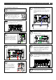
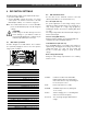
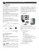
Table Of Contents
- 1 GENERAL INFORMATION
- 2 SAFETY INSTRUCTIONS
- 3 INSTALLATION
- 3.1 Location
- 3.2 Connections
- 3.3 Wiring
- 3.4 Battery capacity
- 3.5 Battery isolator
- 3.6 Connection of second battery (3A output)
- 3.7 Temperature sensor
- 3.8 Voltage sense
- 3.9 Alarm function
- 3.10 RJ12 splitter for enclosure C2
- 3.11 Overview connection compartment
- 3.12 Materials
- 3.13 Connection
- 3.14 Installation step-by-step
- 3.15 Commissioning after installation
- 3.16 Decommissioning
- 3.17 Storage and transportation
- 4 DIP SWITCH SETTINGS
- 5 OPERATION
- 6 MASTERBUS
- 7 TROUBLE SHOOTING
- 8 TECHNICAL DATA

12
Mass 24/50, 24/75, 24/100, 48/25, 48/50 – User and Installation Manual
3.15 Commissioning after installation
Note: When your Mass Charger is not new, you have to
consider that former users may have changed the
settings. Reset the Mass Charger to factory
settings when there is any doubt (see section 6.3
on page 15).
3.15.1 General
The factory settings of the Mass Charger are optimal for
most installations. With some applications however, it is
desirable to change these settings. Therefore, several
adjustments can be made. See chapters 4 and 6.3.
Note: The DIP switches must be adjusted prior to
commissioning. All other settings can only be
configured after commissioning.
CAUTION!
Check the polarity of all wiring before
commissioning: positive connected to positive
(red cables), negative connected to negative
(black cables).
If all wiring is OK, place the DC fuse(s) of the DC
distribution to connect the batteries to the Mass Charger.
WARNING!
When placing this fuse, a spark can occur,
caused by the capacitors used in the Mass
Charger.
Now the Mass Charger is ready for operation. After
switching on the AC power supply the Mass Charger will
initiate the charging process.
3.15.2 MasterBus
Adjustment of the settings of the Mass Charger can be
made by means of DIP switches or via the MasterBus
network (by means of an USB interface connected to a PC
with MasterAdjust software). Some settings can only be
changed via the MasterBus interface. See section 6.3 on
page 15 for an overview of all available MasterBus
settings.
3.16 Decommissioning
If it is necessary to put the Mass Charger out of operation,
follow the instructions in order of succession as described
below:
1 Switch the Mass Charger to OFF.
2 Remove the DC fuse(s) of the DC distribution and/or
disconnect the batteries.
3 Remove the AC fuse(s) of the AC input and/or
disconnect the AC mains.
4 Open the connection compartment of the Mass
Charger.
5 Check with a suitable voltage meter whether the
inputs and the outputs of the Mass Charger are
voltage free.
6 Disconnect all wiring.
Now the Mass Charger can be demounted in a safe way.
3.17 Storage and transportation
When not installed, store the Mass Charger in the original
packing, in a dry and dust free environment.
Always use the original packing for transportation. Contact
your local Mastervolt dealer for further details if you want
to return the apparatus for repair.