
Instruction Manual
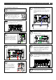
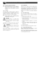
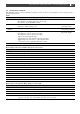
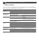
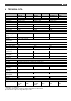
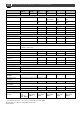
Table Of Contents
- 1 GENERAL INFORMATION
- 2 SAFETY INSTRUCTIONS
- 3 INSTALLATION
- 3.1 Location
- 3.2 Connections
- 3.3 Wiring
- 3.4 Battery capacity
- 3.5 Battery isolator
- 3.6 Connection of second battery (3A output)
- 3.7 Temperature sensor
- 3.8 Voltage sense
- 3.9 Alarm function
- 3.10 RJ12 splitter for enclosure C2
- 3.11 Overview connection compartment
- 3.12 Materials
- 3.13 Connection
- 3.14 Installation step-by-step
- 3.15 Commissioning after installation
- 3.16 Decommissioning
- 3.17 Storage and transportation
- 4 DIP SWITCH SETTINGS
- 5 OPERATION
- 6 MASTERBUS
- 7 TROUBLE SHOOTING
- 8 TECHNICAL DATA

Mass 24/50, 24/75, 24/100, 48/25, 48/50 – User and Installation Manual
11
3.14 Installation step-by-step
1
Mark the position of the mounting spots using
the drilling dimensions.
2
Place the four screws first and
hang the Mass Charger over
them. Then fix the Mass to the
wall by securing the screws.
3
Open the connection compartment by
loosening the two screws.
4
Feed the AC wiring through the
cable gland and connect the
wiring to the screw terminals.
Tighten the cable gland firmly.
5
Connect the DC cabling of the house bank,
positive to +, negative to – .
+ -
6
Option for model 24/50:
Connect the DC wiring of
the second battery bank
(max. 3A). This bank has a
common negative with the
main battery.
7
Attach the battery temperature sensor to the
casing of the main battery bank.
Plug the temperature sensor cable into the
“Temp.Sensor” jack. See also Figure 3 on
page 9.
7
Option: Connect the Mass Charger to the
MasterBus network.
8
The factory setting of the Mass Charger is
optimal for most installations. Sometimes
however, it is desirable to change these
settings. See chapter 4 (page 13) and
section 6.3 (page 15).
9
Check all wiring. If everything is all right,
close the connection compartment by fixing
the two screws.
10
Continue with section 3.15 for
commissioning of the Mass Charger.