
Instruction Manual
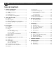
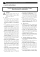

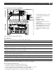
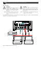
Table Of Contents
- 1 GENERAL INFORMATION
- 2 SAFETY INSTRUCTIONS
- 3 INSTALLATION
- 3.1 Location
- 3.2 Connections
- 3.3 Wiring
- 3.4 Battery capacity
- 3.5 Battery isolator
- 3.6 Connection of second battery (3A output)
- 3.7 Temperature sensor
- 3.8 Voltage sense
- 3.9 Alarm function
- 3.10 RJ12 splitter for enclosure C2
- 3.11 Overview connection compartment
- 3.12 Materials
- 3.13 Connection
- 3.14 Installation step-by-step
- 3.15 Commissioning after installation
- 3.16 Decommissioning
- 3.17 Storage and transportation
- 4 DIP SWITCH SETTINGS
- 5 OPERATION
- 6 MASTERBUS
- 7 TROUBLE SHOOTING
- 8 TECHNICAL DATA

10
Mass Charger 12/75-3, 12/100-3, 24/40-3, 24/60-3 – User and Installation Manual
3.13 Connection
WARNING!
Let installation work be done by a licensed
electrician. Before beginning with the
connection of the wiring, make the AC
distribution as well as the DC distribution
voltage free.
CAUTION!
Too-thin cables and/or loose connections can cause
dangerous overheating of the cables and/or terminals.
Therefore, tighten all connections well, in order to limit
transition resistance as far as possible. Use cables of
the correct size.
Note:
If the battery temperature remains within
15-25°C, the battery temperature sensor is
optional.
Note:
The Mass Charger supports MasterBus and RS 232
compatible remote control panels.
The following schematic illustrates the general placement of the Mass Charger. It is not meant to provide detailed wiring
instructions for any particular electrical installation.
Figure 4. Installation drawing of the Mass Charger
BATTERY BANK 1
(main battery bank)
Temperature sensor
BATTERY BANK 2
Battery
fuse
Battery
fuse
Charger
fuse
L
N
PE/GND
RCD