Mass Charger MASS 24/50-2; 24/50 3ph; 24/75; 24/75 (120V); 24/100; 24/100 3ph; 48/25; 48/50 FULLY AUTOMATIC BATTERY CHARGER USER AND INSTALLATION MANUAL EN For the latest version of this manual, visit our website: NL Ga om deze handleiding in andere talen te downloaden naar onze website: DE Um diese Anleitung in anderen Sprachen herunterzuladen, besuchen Sie bitte unsere Website: FR Pour télécharger ce manuel dans d'autres langues, consultez notre site Web : ES Para descargar este manual en otros
Mass 24/50, 24/75, 24/100, 48/25, 48/50 – User and Installation Manual TABLE OF CONTENTS 1 GENERAL INFORMATION ........................................ 3 1.1 Use of this manual .............................................. 3 1.2 Validity of this manual ......................................... 3 1.3 Liability................................................................ 3 1.4 Identification label ............................................... 3 1.5 Correct disposal of this product .................
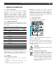
Mass 24/50, 24/75, 24/100, 48/25, 48/50 – User and Installation Manual 3 1 GENERAL INFORMATION 1.1 Use of this manual This manual contains important safety and operating instructions for the safe and effective operation, maintenance and possible correction of minor malfunctions of the Mass Charger.
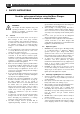
Mass 24/50, 24/75, 24/100, 48/25, 48/50 – User and Installation Manual 2 SAFETY INSTRUCTIONS Read the entire manual before using the Mass Charger. Keep this manual in a secure place. WARNING! This chapter describes important safety and operating instructions for use of a Mass Charger in residential, recreational vehicle (RV) and marine applications. 2.
Mass 24/50, 24/75, 24/100, 48/25, 48/50 – User and Installation Manual 7 8 9 10 11 12 13 14 spark or short-circuit battery or other electrical part and may cause explosion. Remove personal metal items such as rings, bracelets, necklaces, and watches when working with a battery. A battery can produce a short-circuit current high enough to weld a ring or the like to metal, causing a severe burn.
Mass Charger 12/75-3, 12/100-3, 24/40-3, 24/60-3 – User and Installation Manual 3 INSTALLATION 3.3.1 During installation and commissioning of the Mass Charger, the important safety instructions are applicable at all times. See chapter 2 on page 4. Check if the voltage of your mains source or generator corresponds with the AC input voltage of the battery charger as mentioned on the type number plate. See section 1.4 on page 3.
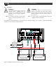
Mass 24/50, 24/75, 24/100, 48/25, 48/50 – User and Installation Manual 3.3.3 DC wiring 3.5 Keep the cable connection between charger and batteries as short as possible. If available, use coloured battery cables. If this is not possible, mark the plus and the minus cables with coloured insulating tape (e.g. red for plus and blue/black for minus).
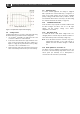
Mass Charger 12/75-3, 12/100-3, 24/40-3, 24/60-3 – User and Installation Manual 3.9 Alarm function Charge voltage (V) To control external equipment, the charger is equipped with a potential free contacts alarm relay; see Figure 3 on page 9. The alarm function has two modes: standard (factory setting) and DC alarm mode (continuous mode). The maximum switch current of the relay is 1A. Exceeding the setpoints will activate the alarm (see page 16). 3.9.1 Standard alarm mode Figure 2.
Mass 24/50, 24/75, 24/100, 48/25, 48/50 – User and Installation Manual C2 ENCLOSURE 3.
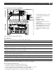
Mass Charger 12/75-3, 12/100-3, 24/40-3, 24/60-3 – User and Installation Manual 3.13 Connection WARNING! CAUTION! Let installation work be done by a licensed electrician. Before beginning with the connection of the wiring, make the AC distribution as well as the DC distribution voltage free. Too-thin cables and/or loose connections can cause dangerous overheating of the cables and/or terminals. Therefore, tighten all connections well, in order to limit transition resistance as far as possible.
Mass 24/50, 24/75, 24/100, 48/25, 48/50 – User and Installation Manual 3.14 Installation step-by-step 1 2 3 Mark the position of the mounting spots using the drilling dimensions. 11 7 Attach the battery temperature sensor to the casing of the main battery bank. Plug the temperature sensor cable into the “Temp.Sensor” jack. See also Figure 3 on page 9. 7 Option: Connect the Mass Charger to the MasterBus network. 8 The factory setting of the Mass Charger is optimal for most installations.
Mass 24/50, 24/75, 24/100, 48/25, 48/50 – User and Installation Manual 3.15 Commissioning after installation 3.15.2 MasterBus Note: When your Mass Charger is not new, you have to consider that former users may have changed the settings. Reset the Mass Charger to factory settings when there is any doubt (see section 6.3 on page 15).
Mass 24/50, 24/75, 24/100, 48/25, 48/50 – User and Installation Manual 13 4 DIP SWITCH SETTINGS The Mass Charger settings can be adjusted in two ways: • By means of DIP switches; • Via the MasterBus network (by means of a remote control panel or an interface connected to a PC with MasterAdjust software); see section 6.3 on page 15.
Mass 24/50, 24/75, 24/100, 48/25, 48/50 – User and Installation Manual 5 OPERATION 5.1 Introduction The Mass charger is a fully automatic, high efficiency battery charger/rectifier. The Mass Charger not only charges batteries rapidly and safely, it supplies the connected consumers at the same time. In addition, the Mass Charger is secured against short circuit, overload and high temperatures in an industrial environment. 5.
Mass Charger 24/50, 24/75, 24/100, 48/25, 48/50 – User and Installation Manual 15 6 MASTERBUS CAUTION! 6.1 About MasterBus Never connect a non-MasterBus device to the MasterBus network directly! This will damage all connected MasterBus devices. All devices that are suitable for MasterBus are marked with the MasterBus symbol. MasterBus is a CAN based, fully decentralized data network for communication between Mastervolt devices.
Mass 24/50, 24/75, 24/100, 48/25, 48/50 – User and Installation Manual Meaning Factory setting Adjustable range (Max current)* 0 – Imax* General Max. current Maximum charge current, dependent. adjustable model Temp. compensate Charge voltage compensation for temperature (V/°C). -0.060/-0.120V/°C -1.000 – 1.000V/°C Output reduction Output reduction that can be used as target event to adjust the maximum current. 0% 0-90% Relay Alarm set points DC Alrm high on Alarm DC High on 32.
Mass 24/50, 24/75, 24/100, 48/25, 48/50 – User and Installation Manual 6.4 17 Event based commands With MasterBus a device can be programmed to initiate an action at another connected device. This is done by means of event-based commands. Events Field Meaning Factory setting Adjustable range Event x source Event-based command. Mass Charger event that should result in an action by another device on the MasterBus network. Disabled See Event source list.
Mass 24/50, 24/75, 24/100, 48/25, 48/50 – User and Installation Manual 7 TROUBLE SHOOTING In case of a failure, the Mass Charger display shows an error ‘code’ to help you find its source. See section 5.6 LED indicators, on page 14. If you cannot solve a problem using the following fault-finding table, contact your Mastervolt dealer. Make sure you have the part and serial number at hand (See section 1.4, on page 3). Malfunction Possible cause What to do No output voltage and/or current No AC input.
Mass 24/50, 24/75, 24/100, 48/25, 48/50 – User and Installation Manual 19 8 TECHNICAL DATA 8.
Mass 24/50, 24/75, 24/100, 48/25, 48/50 – User and Installation Manual Model Mass 24/100 DNV-GL Mass 24/100 Mass 24/50 3ph Mass 24/100 3ph Mass 48/25 Mass 48/50 Product code 40021006 42021006 40030506 40031006 40040256 40040506 INPUT Mains voltage 230V, -10% + 15% 3 x 365...550V 3x 365...
Mass 24/50, 24/75, 24/100, 48/25, 48/50 – User and Installation Manual 8.
8.3 Mass 24/50, 24/75, 24/100, 48/25, 48/50 – User and Installation Manual Characteristics Figure 8. Charge current versus input voltage Figure 9.
Mass 24/50, 24/75, 24/100, 48/25, 48/50 – User and Installation Manual Figure 10. Charge characteristic of the equalize charge cycle (at 25°C/77°F) Figure 11.
Europe, Middle East & Africa Technical Support T: +31 (0) 20 34 22 100 E: ts.emea@OneASG.com Americas & Caribbean Technical Support T: +1 262 293 0600 / 800 307 6702 E: tech.mastervolt@OneASG.com Asia Pacific Technical Support T: +64 9 415 7261 E: technical.apac@OneASG.