
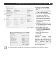
Installation Manual


22
ChargeMaster Plus 24/80-2, 24/110-2 – User and Installation Manual
5 OPERATING INSTRUCTIONS
5.1 Introduction
The ChargeMaster Plus is a fully automatic
battery charger. This means that under normal
circumstances it can be left switched on with AC
power and batteries connected. The
ChargeMaster Plus is suitable for charging of Li-
ion and lead-acid batteries, which may include
maintenance-free, low maintenance, AGM, gel or
deep-cycle batteries. It operates on both 240V
and 120V.
WARNING!
The MLI charging voltages on this
charger fit the Mastervolt Li-ion
(MLI) batteries but do not
necessarily fit other Li-ion
batteries! Always follow the
instructions provided by the
battery manufacturer!
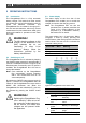
5.2 Switching on / off
The ChargeMaster Plus is activated by keeping
the ON/OFF button pressed for approximately 3
seconds. The MODE LED (item 1 in Figure 5) will
illuminate green. If necessary and if AC power is
available, the ChargeMaster Plus will start to
charge the batteries.
Note: Once switched on, the ChargeMaster
Plus automatically resumes operation
after it was disconnected from an AC
source temporarily.
By holding the ON/OFF button pressed again for
approx. 3 seconds, the ChargeMaster Plus will
switch off: the ChargeMaster Plus stops and the
MODE LED illuminates red. When the
ChargeMaster Plus was switched off, it can only
be activated by pressing the ON/OFF button
again.
WARNING!
Switching the ChargeMaster Plus
off or “stand-by” does not cut off
the connection to the batteries or
the AC source. This means that
voltages are still present inside
the apparatus.
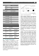
5.3 Status display
The status display at the front side of the
ChargeMaster Plus enables you to control the
charger and monitor the charging process.
Note: The ChargeMaster Plus can also be
monitored from a remote panel like the
Touch 10 (in a CZone network) or the
EasyView 5 (in a MasterBus network).
See section 4.2 for details.
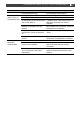
The status display has a 3 level menu. Menu
navigation is done by shortly pressing the
ON/OFF button. After each press the next menu
level is shown. The color of LED 1 indicates the
level that is being shown.
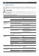
Color LED 1
Menu
Meaning
Green
Level 1
Status menu
Orange
Level 2
Output power menu
Red
Level 3
Error menu
Figure 5: ChargeMaster Plus status LEDs
STATUS MENU
LED
State
Meaning
1
Solid green
ChargeMaster Plus on
Solid red
ChargeMaster Plus
stand-by
Blinking fast
red
Error, navigate to error
menu
2
Blinking fast
green
Battery 1 in bulk stage
Blinking slow
green
Battery 1 absorption
stage
Solid green
Battery 1 in float stage