
Installation Manual

10
ChargeMaster Plus 24/80-2, 24/110-2 – User and Installation Manual
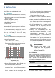
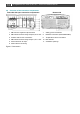
3.6 Overview of the connection compartment
Front side with open connection compartment
Bottom side
1
M8 Common negative output terminal
7
Safety ground connection
2
M6 Positive terminal charge output 2; DC 2 OUT
8
Network connection (CZone/MasterBus)
3
Isolation walls for DC connections
9
Temperature sensor connection
4
M8 Positive terminal charge output 1; DC 1 OUT
10
DIP switches
5
Screw terminals AC input
11
Ventilation openings
6
Strain relief for AC wiring
Figure 2: Connections