CHARGEMASTER PLUS 24/80-2, 24/110-2 AUTOMATIC BATTERY CHARGER USER AND INSTALLATION MANUAL EN NL DE FR ES IT 10000015468/06 For the latest version of this manual, visit our website: Ga om deze handleiding in andere talen te downloaden naar onze website: Um diese Anleitung in anderen Sprachen herunterzuladen, besuchen Sie bitte unsere Website: Pour télécharger ce manuel dans d'autres langues, consultez notre site Web : Para descargar este manual en otros idiomas, visite nuestro sitio web: Per scaricare que
ChargeMaster Plus 24/80-2, 24/110-2 – User and Installation Manual TABLE OF CONTENTS 1 GENERAL INFORMATION ......................... 3 1.1 Use of this manual .................................... 3 1.2 Liability ....................................................... 3 1.3 Warranty .................................................... 3 1.4 Disclaimer .................................................. 3 1.5 Identification label .................................... 3 1.6 Correct disposal of this product ..
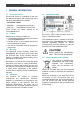
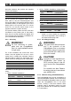
ChargeMaster Plus 24/80-2, 24/110-2 – User and Installation Manual 3 1 GENERAL INFORMATION 1.1 Use of this manual This manual serves as a guideline for the safe and effective operation and maintenance of the following ChargeMaster Plus models: 1.5 Identification label Part number Model 44320805 ChargeMaster Plus 24/80-2 44321105 ChargeMaster Plus 24/110-2 These models are further referred to as “ChargeMaster Plus”. 1.
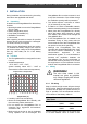
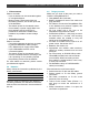
ChargeMaster Plus 24/80-2, 24/110-2 – User and Installation Manual 2 SAFETY INSTRUCTIONS IMPORTANT SAFETY INSTRUCTIONS SAVE THESE INSTRUCTIONS WARNING! Read the entire manual before using the ChargeMaster Plus. Keep this manual in a secure place. This chapter describes important safety and operating instructions for use of a ChargeMaster Plus in residential, recreational vehicle (RV) and marine applications. 2.
ChargeMaster Plus 24/80-2, 24/110-2 – User and Installation Manual BATTERIES GENERATE EXPLOSIVE GASES DURING NORMAL BATTERY OPERATION. FOR THIS REASON, IT IS OF UTMOST IMPORTANCE THAT EACH TIME BEFORE USING THE ChargeMaster Plus, YOU READ THIS MANUAL AND FOLLOW THE INSTRUCTIONS EXACTLY. 2 To reduce risk of battery explosion, follow these instructions and those published by battery manufacturer and manufacturer of any equipment you intend to use in vicinity of the battery.
5 6 7 8 ChargeMaster Plus 24/80-2, 24/110-2 – User and Installation Manual (5). If positive post is grounded to the chassis, see (6). For negative-grounded vehicle, connect POSITIVE (RED) clip from battery charger to POSITIVE (POS, P, +) ungrounded post of battery. Connect NEGATIVE (BLACK) clip to vehicle chassis or engine block away from battery. Do not connect clip to carburetor, fuel lines, or sheet-metal body parts. Connect to a heavy gage metal part of the frame or engine block.
ChargeMaster Plus 24/80-2, 24/110-2 – User and Installation Manual 7 3 INSTALLATION During installation and commissioning, the safety instructions are applicable at all times. 3.1 Unpacking In addition to the ChargeMaster Plus the delivery includes: • Mounting bracket to mount the ChargeMaster Plus to a wall; • Battery temperature sensor; • Drop cable CZone/MB (1m); • MasterBus Terminator; • User manual. After unpacking, check the contents for possible damage. Do not use the product if it is damaged.
ChargeMaster Plus 24/80-2, 24/110-2 – User and Installation Manual distinction between the positive and negative wire from the battery: Wire color Red Black Meaning Positive Negative Connect to: + (POS) – (NEG) Run the positive and negative cables next to each other to limit the electromagnetic field around the cables. The negative cable should be connected directly to the negative post of the battery bank or the ground side of a current shunt. Do not use the chassis frame as the negative conductor.
ChargeMaster Plus 24/80-2, 24/110-2 – User and Installation Manual • CZone network Points to consider: ˗ Up to 40 devices can be connected together on a single backbone. ˗ Make sure the CZone network has two terminating resistors, one at each open end of the backbone. ˗ The electric power for the network comes from a battery or power supply. Make sure that it delivers enough power and is positioned as close to the middle of the backbone as possible to reduce voltage drop.
ChargeMaster Plus 24/80-2, 24/110-2 – User and Installation Manual 3.
ChargeMaster Plus 24/80-2, 24/110-2 – User and Installation Manual 11 3.7 Connection example This schematic illustrates the general placement of the ChargeMaster Plus in a circuit. It is not meant to provide detailed wiring instructions for any particular electrical installation. Figure 3: Installation drawing of the ChargeMaster Plus Notes: - If the battery temperature remains within 15-25°C, connection of the battery temperature sensor is optional. - Lithium-ion batteries require no temperature sensor.
ChargeMaster Plus 24/80-2, 24/110-2 – User and Installation Manual CAUTION! 2 Too-thin cables and/or loose connections can cause dangerous overheating of the cables and/or terminals. Therefore, tighten all connections well, to limit transition resistance as far as possible. Use cables of the correct size. CAUTION! Short circuiting or reversing polarity may lead to serious damage to the batteries, the ChargeMaster Plus, the cabling and/or the terminal connections.
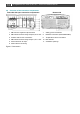
ChargeMaster Plus 24/80-2, 24/110-2 – User and Installation Manual 5 Connect the AC wiring to the screw terminals. Fasten the cable with the strain relief. 6 Integrate a fuse holder in the positive battery wire but do not place the fuse yet! Fit crimp-on cable lugs to the DC cables. Connect the DC cabling of battery bank 1, positive to +, negative to – . Repeat steps for output 2. 13 7 Attach the battery temperature sensor to the casing of battery bank 1.
9 ChargeMaster Plus 24/80-2, 24/110-2 – User and Installation Manual If required, use a small screwdriver to change DIP switch settings. See section 4.1. having flammable materials close by. 3 4 5 10 Check all wiring; see also Figure 3 for wiring details. If all wiring is OK: Place the DC fuses. 6 11 Close the connection compartment by fixing the screws. 12 Continue with section 3.9 for commissioning of the ChargeMaster Plus. 3.
ChargeMaster Plus 24/80-2, 24/110-2 – User and Installation Manual 15 4 SETTINGS Adjustment of the settings of the ChargeMaster Plus can be made in two different ways: • By means of DIP switches. • From a laptop or notebook connected to the ChargeMaster Plus via a USB Interface. Some settings can only be changed in this way. CAUTION! In a MasterBus network: DIP switch 1 must always be set to the ON position (1). DIP switch 2 is MasterBus Powering ON (1) or OFF (0).
4.2.1 ChargeMaster Plus 24/80-2, 24/110-2 – User and Installation Manual Monitoring A remote panel, like the SmartRemote, Touch 10 (CZone) or EasyView 5 (MasterBus), can be used for reading battery information. See applicable user manuals for details. The following table lists the parameters as shown in MasterAdjust.
ChargeMaster Plus 24/80-2, 24/110-2 – User and Installation Manual 4.2.3 17 History The history data shows the absolute maximum readings. The following parameters are only shown in MasterAdjust. Parameter Meaning Charger Days running Total run time in charger mode DC 1 / 2 OUT Total Ah’s 4.2.4 Total charged Ah’s Configuration settings The configuration can be done in MasterAdjust, from a laptop or notebook connected to the ChargeMaster Plus via a Mastervolt USB Interface.
ChargeMaster Plus 24/80-2, 24/110-2 – User and Installation Manual Parameter Bulk Voltage Minimum time Start time at Maximum time Absorption Voltage Maximum time Return Amps Minimum time Float Voltage Return to bulk V Return to bulk sec DC 1 OUT Name Shunt device Meaning Factory setting Value range Bulk voltage (@ 25°C); see section 5.
ChargeMaster Plus 24/80-2, 24/110-2 – User and Installation Manual 4.2.5 19 Events – System automation A CZone/MasterBus device can be programmed to initiate an action at another connected device. This is very helpful in automation of your system but is not required. In MasterBus this is done by means of event based commands. In the Events tab you can program the ChargeMaster Plus to act as an event source.
ChargeMaster Plus 24/80-2, 24/110-2 – User and Installation Manual 4.3 MasterShunt In a MasterBus network, a MasterShunt can be coupled with output 1 (DC 1 OUT) of the ChargeMaster Plus. The actual measurement data of the MasterShunt will be used to charge the batteries. Refer to the manual of the MasterShunt for information on how to configure your system. 4.4 MLI Ultra The ChargeMaster Plus can be combined with an MLI Ultra Lithium-ion battery.
ChargeMaster Plus 24/80-2, 24/110-2 – User and Installation Manual 21 6. Select the required Charge Method from the drop-down list. 7. Enter an understandable Name for DC 1 OUT, DC 2 OUT. 8. From the DC 2 Charge Method drop-down list, select the required mode for DC 2 OUT. See section 5.5. Depending on the selected mode, additional settings will be offered, hidden or grayed out. 9. NMEA2000 Instances are used to differentiate between multiple monitoring sources. 10.
ChargeMaster Plus 24/80-2, 24/110-2 – User and Installation Manual 5 OPERATING INSTRUCTIONS 5.1 Introduction The ChargeMaster Plus is a fully automatic battery charger. This means that under normal circumstances it can be left switched on with AC power and batteries connected. The ChargeMaster Plus is suitable for charging of Liion and lead-acid batteries, which may include maintenance-free, low maintenance, AGM, gel or deep-cycle batteries. It operates on both 240V and 120V.
ChargeMaster Plus 24/80-2, 24/110-2 – User and Installation Manual 4 5 Blinking fast green Blinking slow green Solid green Blinking green Battery 2 in bulk stage Battery 2 absorption stage Battery 2 in float stage Network communication OUTPUT POWER MENU LED State Meaning 1 Solid orange Output power menu Total output power 02 Solid orange 25% Total output power 263 Solid orange 50% Total output power 514 Solid orange 75% Total output power 765 Solid orange 100% LED 1 2 State Blink fast red Blink fast
5.4.1 ChargeMaster Plus 24/80-2, 24/110-2 – User and Installation Manual Charge voltages AGM or GEL Flooded Lithium-ion 5.4.2 Bulk Absorption Float 28.5 28.5 27.6 28.5 28.5 28.5 28.5 26.5 27.0 Pre-float The ChargeMaster Plus can automatically switch each individual output from absorption to prefloat stage. Pre-float ensures batteries that are nearly full do not receive the higher charge voltage needed in the absorption stage.
ChargeMaster Plus 24/80-2, 24/110-2 – User and Installation Manual 5.7 Storage If it is necessary to put the ChargeMaster Plus out of operation, follow the instructions in order of succession as described below: 1 Turn AC power off. 2 Switch off the ChargeMaster Plus (see section 5.2). 3 Remove the DC fuse(s) and disconnect the batteries. 4 Switch the RCD/Breaker of the AC input to the OFF position and, if required, disconnect the AC mains.
ChargeMaster Plus 24/80-2, 24/110-2 – User and Installation Manual 6 TROUBLE SHOOTING The ChargeMaster Plus is protected against overload, short circuit, overheating and under and over voltage. If a fault condition occurs, the LEDs indicate an error code. See section Status display for an explanation. CAUTION! The ChargeMaster Plus is not protected against serious over voltage (>275VAC) on the AC input. If you cannot solve a problem using the fault finding table, contact your supplier or Mastervolt.
ChargeMaster Plus 24/80-2, 24/110-2 – User and Installation Manual Malfunction Remote panel display shows no ChargeMaster Plus Slow or no MasterBus communication 27 Possible cause What to do Charge voltage too high Check settings (see chapter 4) Display is switched off Switch on display, refer to display manual Error in the wiring Check the network cables No terminating device placed at the ends of the network A network needs a terminating device on both ends of the network, check if available
ChargeMaster Plus 24/80-2, 24/110-2 – User and Installation Manual 7 TECHNICAL DATA 7.1 Specifications Model Product code Nominal input voltage Nominal input frequency Full load consumption Max. AC input current (@ 230VAC) Max. AC input current (@ 120VAC) Nominal output voltage Total charge current* Number of battery outlets Max. current DC 2 OUT* Charge characteristic* Charge voltage Bulk* Charge voltage Absorption* Charge voltage Float*; Max. absorption and max.
ChargeMaster Plus 24/80-2, 24/110-2 – User and Installation Manual 7.2 Dimensions Dimensions in mm [inches] ChargeMaster Plus models 24/80-2, 24/110-2. Output power (%) 7.
ChargeMaster Plus 24/80-2, 24/110-2 – User and Installation Manual 3-step+ charging characteristics of flooded batteries Figure 9: 3-step+ charging characteristics of flooded batteries
ChargeMaster Plus 24/80-2, 24/110-2 – User and Installation Manual 31
Copyright © 2020 Mastervolt. All rights reserved. Reproduction, transfer, distribution or storage of part or all of the contents in this document in any form without the prior written permission of Mastervolt is prohibited. Europe, Middle East & Africa Customer Service T: +31 (0) 20 34 22 100 E: info@mastervolt.com Americas & Caribbean Customer Service T: +1 800 307 6702, Option 1 E: orderentry@marinco.com Asia Pacific Customer Service T: +64 9 415 7261 Option 1 E: enquiries@bepmarine.