
Installation Manual

14
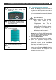
ChargeMaster Plus 12/75-3, 12/100-3, 24/40-3, 24/60-3 – User and Installation Manual
5
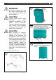
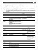
Connect the wiring to the screw
terminals.
Fasten the cable with the strain
relief.
6
Integrate a fuse holder in the positive
battery wire but do not place the fuse
yet!
Fit crimp-on cable lugs to the DC
cables.
Connect the DC cabling of battery
bank 1, positive to +, negative to – .
Repeat steps for output 2 and 3.
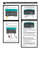
7
Attach the battery temperature
sensor to the casing of battery bank
1. Plug the temperature sensor
cable into the “Temp sense” jack.
Option: Connect the ChargeMaster to
the CZone or MasterBus network.
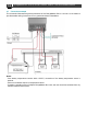
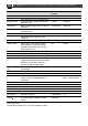
8
Adding to a CZone network
1
Disconnect the backbone at the closest
backbone connection and add in a tee
connector.
2
Reconnect the backbone connection(s)
with the new tee connector in place.
3 Connect the RJ45 CZone/MB drop
cable to the black coupler on the tee
and then connect to the ChargeMaster
Plus.
Adding to a MasterBus network
1 Disconnect a MasterBus cable or
Terminator from the closest MasterBus
device and connect it to the
ChargeMaster Plus.
2 Connect the new MasterBus cable to
the other MasterBus device and then
connect to the ChargeMaster Plus.
Ensure that the network is properly
terminated.