
Use And Care Manual


Page 19
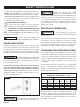
ASSEMBLY
• Attach the rear leg stand assembly A (12) to the rear leg
stand assembly B (13) with hex socket at head screws
M8 x 12 (23).
• Insert the leveling feet (18) into the holes on the rear leg
stand assembly B (13), and tighten with hex nuts M8 (27).
• Thread the adjusting feet (19) into the holes on the rear
leg stand assembly A (12).
• Attach rear leg stand assembly A & B (12, 13) to table saw
assembly (1) and lower leg stand assembly (14) with hex
bolts M8 x 80 (20), spacers (17) and lock hex nut M8 (27).
FIG. 2d
FIG. 2e
FIG. 2f
12
13
14
20
20
17
27
27
17
17
17
27
27
1
12
18
19
13
13
19
12
23
23
18