Manufactured by Holland Marine Parts B.V. Installation manual & user guide Jet Thruster Retrofit installation: www.jetthruster.com RETROFIT MasterCraft Models: X15 / X30 All our products are manufactured according to CE regulations. We keep the rights to change descriptions, graphs or statements, which are required for technical development of our Jet Thruster systems.
“A Jet Thruster will add maneuvrability to your MasterCraft” Complete installation kit available! Boat view single: The operation of the Jet Thruster Single is based on the sucking in of outside water. It is subsequently expelled through nozzles in the bow and/or stern side. To this end the Jet Thruster has been fitted with a powerful centrifugal pump, a three-way valve and electrical controls.
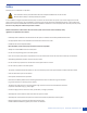
“There isn’t a single boat where this thruster can’t go in” “We have been looking for many years for a thruster system to install in the bigger Mastercraft fleet, finally with the new Jet Thruster we can offer a incredible hassle and noise free maneuverability to our customers and it becomes also a factory Option in all the bigger Models! RETROFIT DIETER HOFER MASTERCRAFT IMPORTER SWITZERLAND MasterCraft: X-30 RETROFIT MasterCraft: X-star Installation manual and user guide MasterCraft / Holland Marine
Warranty provisions On all its newly manufactured products Holland Marine Parts provides quality assurance regarding their proper operation, both with regard to the material and the work done, including latent defects, for a period of 24 months after the invoice date to the first receiver.
Safety: read this prior to installation or operation. This installation manual provides advice about the complete installation of the Jet Thruster. Remarks about safety are accompanied by this symbol. In rare conditions it might be possible that the pump unit of the Jet Thruster does not prime. If you notice a high rpm from the pump unit and no thrust force, do not attempt to prime the pump unit by continuous activating the system.
User Guide Jet Thruster Holland Marine Parts JT-30 Your vessel is equipped with a Holland Marine Parts electric Jet Thruster. For the safe and correct operation of this system Holland Marine Parts recommends every user to carefully study this operating guide. Familiarise yourself with the system by trying it out in various weather conditions. The windage and draught as well as the weight of your vessel are factors contributing to how well the system operates.
Troubleshooting If the system is not functioning: Problem 1.1 System is not working (power indicator off) Cause Solution Joystick not receiving power Press the switch 1.2 System is not working Joystick not receiving power (power indicator off) Check fuse 15A behind joystick 2.1 System is not working (power indicator on) Battery dead or main fuse broken Check / replace fuse 2.
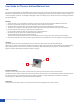
Vertical pump position and absence of intake valve Because of the shallow draft, there is no butterfly valve. This to keep the pump house as close to the hull as possible. The pump is directly installed on angled intake flange which is bolted to the hull. A ball valve is directly installed behind the pump outlet. Pumpunit JTVS-30-00 3-Way valve JTVS-30-00 V-101-00 Water intake assembly Butterfly valve 4” Pressure hose 2”/51mm Hose clamp 48-60 mm.
1: Preparation: Position of Angled Flange - Find a place as deep under the waterline as possible Measure the angle which enables a vertical position of pump unit Order the appropriate flange. Available flanges: 0, 15, 25, 35 degree Rotate the flange to determine where to drill This rotation/positioning will determine how the pump outlet will eventually will be in the boat! Carefully mark where to drill the inlet and the 8 bold holes Drill perfectly without tolerance.
2: Drilling 10 Drill the Central inlet with a Ø 105 mm drill Drill the 8x holes bolds for inlet studs. Use a Ø 13 mm drill Dry fit the Water inlet Flange and verify it mates with the inside Angled Flange.
3: Preparation for Water Inlet Flange - For better hydrodynamics: It is possible to grind the edge of the inlet flange. These modification are custom and depend on the installation and the position of the flange in the hull. Now is the time to perform these custom modifications, after installation this is very difficult. Thoroughly clean the stainless steel parts prior to the application of the Sikaflex 291i adhesive.
4: Installation of Water Inlet Flange Outside the boat: - Use sufficient Sikaflex! Seal it like a Boss…By tightening the nuts on the inside of the vessel, surplus Sikaflex will be pressed out. - Remove the adhesive and support the Water inlet Flange. Inside the boat: - 12 Apply Sikaflex 291i on the hull before the Angled flange mates with the Water Inlet Flange Thoroughly apply Sikaflex 291i to all bolds from the Water Inlet Flange Thoroughly tighten all 8 nuts.
5: Preparation of the Pump Head The pump head will mate with the Angled flange. Between the Angled flange and the pump head there is a o-ring to provide sealing. Caution: 8 holes with conical shaped cavities are cut the pump head. Each hole has a thread cut into the plastic. Tighten thoroughly, but not over-tighten to prevent damage to this thread.
6: Placement of the pump motor Look for the marks on pump head and pump motor! These must mate! 14 - Carefully slide the pump motor in the pump head, check for the marks to mate them correctly. - Make sure the O-ring is attached to the impeller flange of the motor - Apply provide pump house bolds and nuts and tighten with 9 Nm max.
7 : Placing pump outlet and valve - Directly to the pump outlet side: Attach pump outlet part with air nipple socket on top side. Place 2” BSP ball Valve 8: Placing the Air Valve - Connect the Air Valve with the socket on pump outlet. Make sure the electrical solenoid of the Air Valve is placed well above the waterline. - Continue with positioning of 3-Way Valve. Continue with installation of nozzles and hoses Continue with Electrical installation.
Installing the electrical air valve Operation: The pump head of the Jet Thruster system must be installed under the water line in order to prime this centrifugal pump. In some limited cases of fast moving vessels a vacuum can be produced when the nozzles rise above the waterline and the intake remains in the water. The suction under the fast moving hull will retract the present water from the Jet Thruster system.
Water to 3-way valve/nozzle Example of a contactor support on pump unit air leading out of vessel X - Blue ground - Brown 12V F - Yellow/green not in use F G Position of electrical valve must be above water line. Flexible hose, Ø 8mm Picture of contactor support is example. Select applied contactor support and position of F (+12V) and G (Ground) according to the pump unit the installation is applied for. See appendix A1 - F1 Pump unit A Remove plug from pump outlet to connect flexible hose.
9: Position of 3-way valve CAUTION: Prevent physical injury! When electrically turning the plunger present in the valve body, considerable force occurs. Prevent any body parts from getting trapped during installation. Please note: By opening the lit of the valve, the watertight seal and bearing is broken. Opening the valve will void your warranty. • Place of the 3-way valve as close to the nozzles as possible. • Mount the 3-way valve to the vessel.
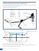
10 Installing the nozzles The Jet Thruster will be most effective when the nozzles are placed AS FAR AS POSSIBLE TO THE FRONT OF THE BOW. (shifted position possible as seen in diagram, to increase leverage arm). Top side of nozzle below waterline. Keep in mind that when the nozzles rise above the waterline , it is possible by the powerful Jet of water expelled by the Jet Thruster inconvenience or damage may occur.
10 Installing the nozzles In case of steel or aluminum vessel plating weldable nozzles are available. For polyester and wooden vessel plating flange treaded nozzles are available. 1: Place vessel horizontal. Select optimum position for nozzle: As far to the front of bow or stern as possible, top side of nozzle 10cm / 4” below water line. Nozzle horizontal and in 90˚ angle to the heart line of the vessel.
7: Outside of vessel: Flange treaded nozzle: In case of an rough or not entire flat surface: Apply sealant for maritime purposes: Sikaflex-291i / 3M 5200 adhesive / sealant on the side of the flange of the nozzle that contacts the vessel plating. In case of a smooth and flat surface: Apply the provided rubber seal. Do not use additional sealant in combination with the rubber seal. Inside vessel: Place the PVC guide ring, white nylon ring and the 2” nut, apply sealant. Tightly fasten the nut.
Electrical installation JT-30 Do not run the pump without the presence of water! 3-way valve Jet Thruster Single CDE 22 Holland Marine Parts / MasterCraft | Installation manual and user guide
Positive / Electrical Air valve to: F F G: Connect with battery minus E to valve Negative / Electrical Air valve to: G G (-) GROUND D C A to joystick B Battery Cable connection to Pump unit: (+) 12V - Battery Positive to free contact at contactor relay - Connect A cable from pump unit to battery negative Contactor support on pump unit Fuse 425A Note: Battery cable length max. 1m/3.3ft Note: Use a battery with high cold cranking amps.
Holland Marine Parts / MasterCraft | Installation manual and user guide
Drill pattern Water inlet / Angled Flange Jet Thruster JT30 Vertical (MasterCraft Retrofit kit only!) 12 ,5 90 185 210 Project & Description Installation manual and user guide Template drill pattern Water inlet MasterCraft Retro fit MasterCraft Holland ANGLES Marine Parts DIMENSIONS IN/MILLIMETERS, IN DEGREES TOLERANCES±0.2mm, ±1º UNLESS OTHERWISE SPECIFIED 0.03 0.03 0.2 0.2 0.2 Ra 3.
US Marine Products 25 Constitution Drive, Taunton, MA 02780 Phone: 508 802-6035 • Fax: 508 802-6006 www.usmarineproducts.com • sales@usmarineproducts.com All our products are manufactured according to CE regulations. We keep the rights to change descriptions, graphs or statements, which are required for technical development of our Jet Thruster systems.