
Installation Instructions
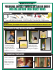

PREHUNG SINGLE-SWING EXTERIOR DOOR
a
)
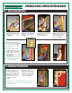
All Mastercraft doors are set up
with a 2-1/8" bore hole set at either
a 2-3/8" or a 2-¾" backset (depend-
ing on door size). All crossbores are
set for a 1" drivepoint latch. This
is done to allow installers to utilize
drive point latch systems, radius plate
systems, or square plate systems.
b
)
To install the backset as a drive-
point system, simply follow the lock
manufacturers instructions for convert-
ing to a drivepoint. Hammer the
drivepoint into place making sure the
angled portion of the backset faces
the jamb
(
fig.21
)
.
c
)
Using the manufacturers
instructions, install the lockset
(
fig.22
)
.
d
)
Install the strike plate on the jamb
(
fig.23
)
. Our
jambs are mortised for a ¼" radius strike plate. If the
lock manufacturer has supplied a square plate, use a
chisel to remove the excess wood material from around
the corners of the plate.
e
)
For doors that are bored for a deadbolt, install
the deadbolt strike plate. If the door does not have
a deadbolt, install a plastic deadbolt cover plate
(
fig.24
)
.
a
)
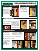
Open the door carefully and
re-check for plumb. Finish screwing the
hinge jamb into place by removing
one screw from the middle and
bottom hinges and installing a
2-½" drywall screw into those
hinges at the shim locations
into the rough opening. Install
a second 2-½" screw into the
top hinge to prevent the door
from sagging
(
fig.16
)
.
a
)
Re-check plumb on the lock
jamb. Install one 2-½" drywall
screw at the three corresponding
shim locations along the lock jamb
into the rough opening. Carefully,
fold back the weatherstrip to
conceal the screw head.
(
fig.17
)
.
The screw hole can be filled for a
more finished look.
a
)
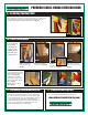
Close the door unit and re-check
the margin around the door unit, it
should be even horizontally across the
top of the header and vertically
from the header to the sill. Make
adjustments to the shimming as
needed.
(
fig.18
)
.
b
)
If your prehung unit has an adjustable
sill: Using a #2 phillips screw driver,
adjust the set screws on the top of the
sill crown to allow your door to operate
properly
(
fig.19
)
. A good test for the
compression of the sweep on the sill
crown is to 1.) Close the door on a piece
of paper. 2.) Pull the paper from between
the sweep and the threshold
(
fig.20
)
.
If the paper tears, the threshold is
adjusted too high and it will prematurely
wear out the sweep. If there is no tension
on the paper, then there will be potential
for water leakage.
8
)
Installing the Lockset
5
)
Fastening the Hinge-Side Frame
6
)
Fastening the Lock-Side Frame
7
)
Adjusting the Frame
g. 16
g. 19
g. 17
g. 18
g. 20
g. 21
g. 23 g. 24g. 22