
Installation Instructions
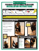

PREHUNG CENTER HINGE PATIO DOOR
a
)
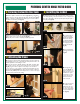
Close the door unit and re-check the margin around the door unit, it should be
even horizontally across the top of the header and vertically from the header to the
sill. Make adjustments to the shimming as needed.
b
)
If your patio unit has an adjustable sill: Using a #2 phillips screw driver, adjust
the set screws on the top of the sill crown to allow your door to operate properly
(
fig.23
)
. A good test for the compression of the sweep on the sill crown is to
1.) Close the door on a piece of paper. 2.) Pull the paper from between the sweep
and the threshold.
(
fig.24 & 25
)
. If the paper tears, the threshold is adjusted too
high and it will prematurely wear out the sweep. If there is no tension on the paper,
then there will be potential for water leakage.
8
)
Installing the Lockset
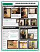
7
)
Adjusting the Frame
g. 23
g. 24
a
)
Re-check for plumb on the inactive side of the door
(
fig.19
)
. Using a 1/8
"
drill bit,
predrill a 1/8
"
hole at a 45º angle, through the jamb and into the shim location
(
fig.20
)
.
b
)
Using a countersink bit, countersink the holes drilled in figure 20 in order to allow the
screw heads to sit flush with the jambs
(
fig.21
)
.
c
)
Install one 2-½
"
wood screw into each of the predrilled locations. Be careful not to over
tighten the screws so that you do not crack the jambs
(
fig.22
)
.
d
)
Repeat this process for the three corresponding head jamb hinge locations.
6
)
Fastening the Inactive Door Jamb
g. 25
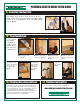
a
)
All Mastercraft doors are set up with a 2-1/8
"
bore hole set at either a 2-3/8
"
or
a 2-¾
"
backset (depending on door size). All crossbores are set for a 1
"
drivepoint latch.
This is done to allow installers to utilize drive point latch system, radius plate systems, or
square plate systems
(
fig.26
)
.
b
)
To install the backset as
a drivepoint system, simply
follow the lock manufacturers
instructions for converting
to a drivepoint. Hammer the
drivepoint into place making
sure the angled portion of
the backset faces the jamb
(
fig.27
)
.
c
)
Using the manufacturers
instructions, install the lockset
(
fig.28
)
.
d
)
Install the strike plate
on the jamb
(
fig.29
)
Our
jambs are mortised for a ¼
"
radius strike plate. If the lock
manufacturer has supplied
a square plate, use a chisel
to remove the excess wood
material from around the
corners of the plate
.
e
)
For doors that are bored
for a deadbolt, install the
deadbolt strike plate. If the
door does not have a dead-
bolt, install a plastic deadbolt
cover plate included with the
door.
(
fig.30
)
.
g. 30
g. 26
g. 27
g. 28
g. 29
g. 30
g. 19 g. 20
g. 22
g. 21