
Owner manual
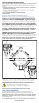


wet bulb and outdoor dry bulb. (Refer to diagram.)
GENERIC TARGET SUPERHEAT & SUBCOOLING CHARTS*
*The required superheat chart is an example of a generic superheat chart of a typical fixed
orifice, split residential system. The required subcooling chart is an example of a typical
chart for a TXV, split residential system. These charts should not be used for charging.
They are only examples to show what the manufacturer’s charts may look like. Follow all
manufacturer’s indications, instructions and warnings above those in this manual.
The indoor wet bulb measurement should be taken as close to the evaporator coil
inlet as possible. The outdoor dry bulb reading should be taken as close to the
condenser air inlet as possible.
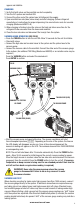
CLEANING THE SENSOR (SEE FIG. D)
Observe the gasket after each vacuum. If oil is present, it is possible that there is a
presence of oil in the sensor chamber.
Follow these instructions:
1. Disconnect the sensor chamber from the socket.
2. Remove the gasket & depressor from the assembly to clean.
3. Clean the gasket. Rinse the sensor chamber with acetone. Repeat until the oil is
completely removed. Allow 2 – 4 hours for all of the parts to dry.
4. Reassemble all of the parts and check the unit.
PARTS AND ACCESSORY LIST (SEE FIG. E)
34219 Complete Stem Assembly w/Knob (2 pcs)
42010 Gasket for 1/4” FL
42016 Screw Type Depressor
85211 Knob only, Low Side (Blue)
85212 Knob only, High Side (Red)
85215 Piston Seal O-Rings (4 pcs)
85216 Piston Seal Assembly w/O-Rings (2 pcs)
85217 Stem O-Ring (2 pcs)
85218 Stem, Nut and Stem O-Ring
98061-SENSOR Sensor Assembly
98062-001 Vacuum Sensor Cable (only)
99332 1/8 NPT x 1/4 F Flare Swivel Adapter
OPTIONAL ACCESSORIES (SEE FIG. F)
52232 Humidity Temperature Meter
52336 Clamp-On Thermocouple
98062 Complete Vacuum Sensor & Cable Assembly
98210-A Accu-Charge II Electronic Refrigerant Scale
99333 1/4 FL-M x 1/4 FL-M x 1/4 FL-F Tee
99334-110 110V AC/DC Adapter
99334-220 220V AC/DC Adapter (schuko plug)
6
50
52
54
56
58
60
62
64
66
68
70
72
74
76
55
9
12
14
17
20
23
26
29
32
35
37
40
42
45
60
7
10
12
15
18
21
24
27
30
33
35
38
40
43
65
6
10
13
16
19
21
24
27
30
33
36
38
41
70
7
10
13
16
19
21
24
27
30
33
36
39
75
6
9
12
15
19
21
24
28
31
34
37
80
5
8
12
15
18
21
25
28
31
35
85
8
12
15
19
22
26
30
33
90
5
8
13
16
20
24
27
31
95
5
10
14
18
22
25
29
100
8
12
15
20
23
27
105
5
9
13
17
22
26
110
6
11
15
20
25
115
8
14
18
23
57
59
61
63
65
67
69
71
73
75
25
24
23
22
21
20
19
18
17
80
24
23
22
21
20
19
18
17
15
85
23
22
21
20
19
18
16
15
14
90
22
21
20
19
18
16
15
14
12
95
21
20
19
18
17
15
13
12
10
100
20
19
18
17
15
13
12
10
8
105
19
18
17
16
14
12
10
8
6
110
17
16
15
13
12
10
8
6
4
115
15
14
13
12
10
8
6
4
2
DEPRESSOR (PART # 42014)
GASKET (PART # 42010)
1/4” FL-F Swivel Nut
SENSOR TUBE
SENSOR CHAMBER
SOCKET
CABLE
FIG. D
www.mastercool.com