
User manual
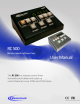

Masterclock RC 500 User Manual – v2014.01.01
9
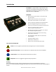
Do not connect more than one RC
500 to the same splitter. The RC500
can control up to six digital clocks.
Operation – Input/Output
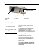
OVERVIEW
The RC500 is a programmable, single-channel, timer
control unit. The RC500 will communicate with single or
multiple TCDS and NTDS digital time displays or it may
stand alone.
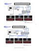
RS485 COMMUNICATION
TCDS series of digital time displays are connected to the
RC500 using the RJ12 port and a 6 wire (6P6C) straight-
through modular cable.
Time stamps are sent to the RC500 every several
seconds. The accuracy of the time is dependent upon the
referenced time in the TCDS.
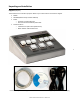
To control multiple remote clock displays using a single
RC500, connect each remote clock display and the RC500
to a 6P6C male splitter (shown at left). Any remote
display connected will receive commands sent from the
RC500.
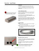
6-WAY SPLITTER
RC500 - Connect one end of a 6P6C cable to the RC500
and the other end to a splitter.
TCDS - Connect one end of a 6P6C cable to a TCDS digital
time display and the other end to the same splitter
as the RC500.
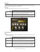
NTP (Network Time Protocol)
NTP driven clock displays are connected to the RC500 on
a local Ethernet network using the RJ45 port and a CAT5
Ethernet patch cable.
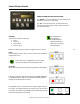
Assigning the remote clock displays to your RC500 is
done within the software application, WinDiscovery
(page 16).
Please refer to the “Configuration” section of this
document for details on using WinDiscovery and
assigning remote clock displays to a RC500.