
User manual

Masterclock RC 500 User Manual – v2014.01.01
5
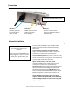
Connections
Network Installation
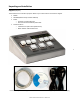
You may install the RC500 on your desk top. Attach
power and communication at the back according to
these specs:
If you ordered a PoE (Power over Ethernet) unit,
plug in the CAT5 Ethernet patch cable for power and
communication input/output to the RJ45 port.
If you ordered AC power, plug in the AC cord into its IEC
socket (customized for your country). All AC power cords
have a standard IEC female plug on one end and a
country specific male plug on the other.
When using AC power, do not also use PoE.
Instead use a 6P6C modular cable (TCDS series) for
communication input/output to the RJ12 port.
The enclosed CD contains a pdf of this User Manual and
discovery/communication/configuration Microsoft
Windows-based software called WinDiscovery. If you
have not already downloaded WinDiscovery for another
Masterclock product, you should do so now for your
RC500. See page 16.
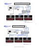
On the following page (p.6) are two sample wiring
diagram solutions using the RC500, one for NTDS along
with a TCDS digital display clock and one for only NTDS
digital display clocks.
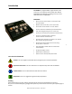
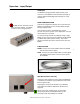
IEC socket
AC power (optional)
This socket will not
appear on NTP
models
RJ12 port
RS485 communications
(TCDS series digital
time display)
RJ45 port
Ethernet communications
(NTP series digital time display)
PoE (optional)
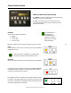
Some users will connect their RC500
to a network for external time
reference.
Others will use their RC500 ‘as is’ by
simply plugging it in. If you do not use
network inputs, please refer to the
Standalone Instructions on page 13.
The back of the RC 500 with power and
communication sockets