
User manual


Masterclock RC 500 User Manual – v2014.01.01
34
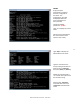
Reset Configuration through pinhole
1. Located on the rear of the unit is the pinhole to the reset
button (i.e. next to the RJ45 Ethernet port).
2. While the unit is powered on, insert a non-metallic reset
tool straight through the pinhole and hold the button for
proximity 5 seconds or until the display shows dashes.
The unit will go through an initialization process and will show the time on the display when reset is
complete.
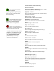
STATUS
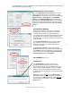
At the bottom left of the “RC 500 Device Settings”
window is the [Status] button. The “RC 500 Status”
window includes a “Display Snapshot” of a graphic
digital clock representing the face of the actual RC 500 in
real time. On the right appear the “UTC Time” and date,
“Local Time” and date, the “Current Reference” signal
(in this case GPS), the “Reference Status” (in this case
“Locked”) and two windows listing “Last Time Lock Lost”
and “Last Time Lock Restored.”
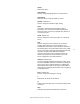
Below these listings are tabbed windows for “Network,”
“NMEA,” “and “NTP.”
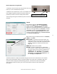
Network Tab ─ includes the name of the device, the
model of the device and a summary of the network
configuration, much of this data is repeated from the
network configuration window described earlier
(page 20).
NMEA Tab ─ Default set to enabled.
NTP Tab ─ includes a checkbox for an enabled NTP
server, plus the number of NTP requests service and
the server stratum. Also includes a checkbox for an
“Enabled” NTP client including indications for the
“Active Server,” the “NTP Status,” the “Last NTP
Time Stamp,” the “Largest Time Adjustment” and
the “Average Time Adjustment.”
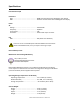
The Status window is a display-only window that gives you the current information on the network
device and synchronization activity. This status update is not precise, but is intended to give you a
view of the device display for troubleshooting purposes. The Status also shows the active NTP
server; primary and/or secondary, the current synchronization status and time adjustment
information.
Reset button through pinhole