
Application Guide

HIGH-TEMP LIMIT SAFETY SHUTOFF (HTL) ACCESS/REPLACEMENT
ACCÈS AU DISPOSITIF DE PROTECTION CONTRE LA SURCHAUFFE (DPS) ET REMPLACEMENT
ACCESO/REEMPLAZO DEL APAGADO DE SEGURIDAD DEL LÍMITE DE ALTA TEMPERATURA (LAT)
REMOVAL:
• Turn the appliance off.
• Unplug the appliance from any power source.
• Locate the access panel for the HTL on the back of the appliance. See Figure A1.
• Remove the access panel.
• Unplug the two (2) connectors from the HTL (top and bottom). See Figure A2.
• From inside the appliance, remove the two (2) screws that mount the HTL to the appliance. See Figure A3.
• Remove the HTL from the appliance.
INSTALLATION:
• Confi rm the appliance is powered off and not plugged into a power source.
• Locate the access panel for the HTL on the back of the appliance. See Figure A1.
• Place the HTL in the proper location. See Figure A2.
• Insert the two (2) screws and remount the HTL to the appliance from the inside. See Figure A3.
• Plug the two (2) connectors to the HTL (top and bottom). See Figure A2.
• Reattach the access panel on the back of the appliance. See Figure A1.
ENLÈVEMENT :
• Éteignez l’appareil.
• Débranchez l’appareil de sa source d’alimentation.
• Trouvez le panneau d’accès du DPS qui se trouve à l’arrière de l’appareil. Voir la fi gure A1.
• Enlevez le panneau d’accès.
• Débranchez les deux (2) connecteurs du DPS (haut et bas). Voir la fi gure A2.
• À partir de l’intérieur de l’appareil, enlevez les deux (2) vis qui fi xent le DPS à l’appareil. Voir la fi gure A3.
• Retirez le DPS de l’appareil.
INSTALLATION :
• Vérifi ez que l’appareil est éteint et n’est pas branché sur une source d’alimentation.
• Trouvez le panneau d’accès du DPS qui se trouve à l’arrière de l’appareil. Voir la fi gure A1.
• Installez le DPS au bon endroit. Voir la fi gure A2.
• Insérez les deux (2) vis et fi xez de nouveau le DPS à l’appareil en passant par l’intérieur. Voir la fi gure A3.
• Branchez les deux (2) connecteurs du DPS (haut et bas). Voir la fi gure A2.
• Remettez le panneau d’accès à l’arrière de l’appareil. Voir la fi gure A1.
REMOCIÓN:
• Apague la unidad.
• Desenchufe la unidad de cualquier fuente de energía.
• Ubique el panel de acceso para el LAT en la parte posterior de la unidad. Ver Figura A1.
• Retire el panel de acceso.
• Desenchufe los dos (2) conectores del LAT (superior e inferior). Ver Figura A2.
• Desde el interior de la unidad, retire los dos (2) tornillos que montan el LAT en la unidad. Ver Figura A3.
• Retire el LAT de la unidad.
INSTALACIÓN:
• Confi rme que la unidad esté apagada y no enchufada a ninguna fuente de energía.
• Ubique el panel de acceso para el LAT en la parte posterior de la unidad. Ver Figura A1.
• Coloque el LAT en el lugar apropiado. Ver Figura A2.
• Inserte los dos (2) tornillos y vuelva a montar el LAT en la unidad desde el interior. Ver Figura A3.
• Enchufe los dos (2) conectores al LAT (superior e inferior). Ver Figura A2.
• Vuelva a fi jar el panel de acceso a la parte posterior de la unidad. Ver Figura A1.
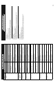
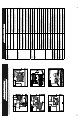
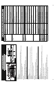
Figure A1
Tool needed for access and replacement: Phillips Head Screwdriver. Outils requis pour l’accès et le remplacement: tournevis cruciforme.
Herramienta necesaria para acceso y reemplazo: Destornillador en cruz
Figure A3Figure A2
7
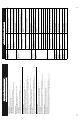
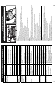
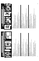
Tool needed for access and replacement: Phillips Head Screwdriver. Outils requis pour l’accès et le remplacement: tournevis cruciforme.
Herramienta necesaria para acceso y reemplazo: Destornillador en cruz
Figure B1 Figure B2
REMOVAL:
• Turn the appliance off.
• Unplug the appliance from any power source.
• Locate the access panel for the PCB on the bottom of the appliance. See Figure B1.
• Remove the access panel.
• Unplug the fi ve (5) PCB assembly connectors from the body. See Figure B2.
• Remove the four (4) screws that mount the PCB to the appliance. See Figure B2.
• Remove the PCB from the appliance.
INSTALLATION:
• Confi rm the appliance is powered off and not plugged into a power source.
• Locate the access panel for the PCB on the bottom of the appliance. See Figure B1.
• Plug the fi ve (5) PCB assembly connectors into the appropriate body connectors. See Figure B2.
• Place the PCB in the proper location. See Figure B2.
• Insert the four (4) screws and remount the PCB to the appliance. See Figure B2.
• Reattach the access panel on the bottom of the appliance. See Figure B1.
ENLÈVEMENT :
• Éteignez l’appareil.
• Débranchez l’appareil de sa source d’alimentation.
• Trouvez le panneau d’accès de la CCP qui se trouve à l’arrière de l’appareil. Voir la fi gure B1.
• Enlevez le panneau d’accès.
• Débranchez du bâti les cinq (5) connecteurs d’assemblage de la CCP. Voir la fi gure B2.
• Enlevez les quatre (4) vis qui fi xent la CCP à l’appareil. Voir la fi gure B2.
• Retirez la CCP de l’appareil.
INSTALLATION :
• Vérifi ez que l’appareil est éteint et n’est pas branché sur une source d’alimentation.
• Trouvez le panneau d’accès de la CCP qui se trouve sur le fond de l’appareil. Voir la fi gure B1.
• Branchez les cinq (5) connecteurs d’assemblage de la CCP dans les connecteurs appropriés sur le bâti. Voir la fi gure B2.
• Installez la CCP au bon endroit. Voir la fi gure B2.
• Insérez les quatre (4) vis pour fi xer la CCP à l’appareil. Voir la fi gure B2.
• Remettez le panneau d’accès sur le fond de l’appareil. Voir la fi gure B1.
REMOCIÓN:
• Apague la unidad.
• Desenchufe la unidad de cualquier fuente de energía.
• Ubique el panel de acceso para la CME en la parte inferior de la unidad. Ver Figura B1.
• Retire el panel de acceso.
• Desenchufe los cinco (5) conectores de ensamblaje de la CME del cuerpo. Ver Figura B2.
• Retire los cuatro (4) tornillos que montan la CME a la unidad. Ver Figura B2.
• Retire la CME de la unidad.
INSTALACIÓN:
• Confi rme que la unidad esté apagada y no enchufada a una fuente de energía.
• Coloque el panel de acceso para la CME en la parte inferior de la unidad. Ver Figura B1.
• Enchufe los cinco (5) PCB conectores de ensamblaje de la CME en los concetores apropiadosdel cuerpo. Ver Figura B2.
• Coloque la CME en la ubicación apropiada. Ver Figura B2.
• Inserte los cuatro (4) tornillos y vuelva a montar la CME en la unidad. Ver Figura B2.
• Vuelva a fi jar el panel de control en la parte inferior de la unidad. Ver Figura B1.
8
POWER CONTROL BOARD (PCB) ACCESS/REPLACEMENT
ACCÈS À LA CARTE DE CONTRÔLE DE PUISSANCE (CCP) ET REMPLACEMENT
ACCESO/REEMPLAZO DE CAJA DE MANDO ELÉCTRICA (CME)