
Installation Guide
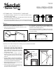
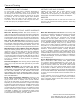
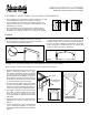

Figure 2
BATH STORAGE CABINETS / WALL HUTCHES]
Depending on the model, matching crown moulding may be included with the cabinet.
• Options for crown attachment: #6 x 3/4 in.
wood screws or brad nails. To install, simply set
the moulding on top of the cabinet. Make sure
the moulding is aligned side to side on the face
frame. Additionally, make sure the front, bottom
edge of the crown moulding lines up with the
outer edge of the door.
• If using wood screws, pre-drill a pilot hole
through the crown into the face frame with a
1/8 in. drill bit then secure the crown to cabinet
(Figure 3).
• To hang cabinet, it will first be necessary to
locate the studs in the wall (in some cases where
a stud location will not work, it will be necessary
to choose the appropriate wall hardware).
• After locating the studs, you will need to pre-drill
holes through the back panel.
• Place the cabinet into place, and using a #12 x
3 in. wood screw, secure the cabinet to the wall
through the back panel (Figure 4).
DETERMINE WALL TYPE AND SELECT HARDWARE
• For wall stud installation, insert #12 x 3 in. screws with washers into the
stud locations (not included).
• For drywall installation, drill holes at the appropriate locations and insert
toggle bolts with washers (not included).
• For concrete wall installation, drill 1/4 in. holes at the appropriate locations
and insert #12 wall anchors, followed by #12 x 3 in. screws (not included).
• If you choose to use hanging wire (not included), it must
be capable of supporting 75 lbs. minimum. Attach wire to
brackets as shown below (Figure 2).
• Once the mounting hardware is installed, hang the mirror
from the hardware using the hanging brackets or the hanging
wire (not included).
INSTALLING THE HANGING BRACKETS
• Attach the hanging brackets to the back of the mirror using
the included screws (Figure 1).
Mirrors
VISTA SUPERIOR
TOP VIEW
Use tornillos de ¾ pulg
(no se incluyen)
Marco frontal
Face frame
Use 3/4" screw
(not included)
Suggested
hole
locations
Ubicaciones
de los
orificios
sugeridas
Figure 4Figure 3
Figure 1
WALL INSTALLATION
Hardware for installation not included.
U180215A
Rev. 03-15