DIGITAL MULTIFUNCTION METER User Manual MT-DP96MF Version 1.
Thanks for choosing our product – MT-DP96MF, Please read this manual carefully and pay attention to below caution matters.
CONTENTS 1. 2. 3. 4. 5. Function introduction…………………………………..4 Technical parameter…………………………………...5 Installation and correction……………………………..6-7 Display and buttons…………………………………….8-13 Programme operation………………………………….
1.
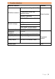
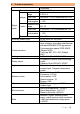
2. Technical parameter Parameter Connection system 3P3W/ 3P4W Measurement range 519V L-L Voltage Over load Continous: 1.2 Vn; Instantaneous: 2Vn Power consumption 1VA Measurement Signal Current range 5A/ 1A Input/ Over load Continous: 1.2In; Instantaneous: 2In Power consumption 1VA Frequence Auxiliary power suply Communication Analog output Relay output Digital input Measure class IP protection Evernionment Safe 45 - 65Hz AC85-265V DC100-300V RS485 communication port, physical layer isolation.
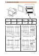
3. Installation and correction LxH (mm) AxB (mm) SxY (mm) SxY (mm) IP65 N (mm) M (mm) 96x96 90.5x90.5 91x91 91.5x91.
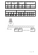
Active Pulse Reactive Pulse RS485 Aux.
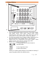
4. Display & Buttons 1a b c d a. b. c. d. Four lines digital display measure information: Three phase voltage, three phase current, active power, reactive power, power factor,frequence, switch input, output, other switch input, two way actice power, two way reactive power, analog input, demand K is light mean practice value is display value is 1.000 times. M is light mean practice value is display value is 1.000.
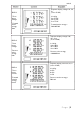
tabe 6 DISP=1 -Three phase voltage -Forward active energy Kwh DISP=2 Seperate display voltage Ua, Ub, Uc (in the 3P4W) In left fig. Ua=5774V Ub=5774V Uc=5774V Forward active energy = 2908.05KWh Seperate display voltage Uab, Ubc, Uca (in the 3P4W) -Three phase voltage In left fig. Uab=10KV Ubc=10KV Uac=10KV -Reverse active energy Kwh Reverse active energy =1000.02Kwh Seperate display current Ia, Ib, Ic (in the 3P4W) DISP=3 -Three phase current -Forward reactive energy Kvarh In left fig.
DISP=4 -Total active power -Total reactive power -Total apparent power DISP=5 - Active power phase A -Reactive power phase A -Apparent power phase A DISP=6 - Active power phase B -Reactive power phase B -Apparent power phase B Total active power = 86.6KW Total reactive power = 0000Kvar Total apparent power =86.6KVA Reverse reactive energy =100.08Kvarh Active power of phase A = 28.87KW Reactive power of phase A = 0000Kvar Apparent power of phase A =28.87KVA Forward active energy =2908.
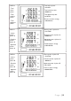
DISP=7 - Active power phase C -Reactive power phase C -Apparent power phase C Active power of phase C = 28.87KW Reactive power of phase C = 0000Kvar Apparent power of phaseCB =28.87KVA Forward reactive energy =50.00KVARh DISP=8 Average current = 5A - Average current Zero sequence current = 0.06A -Zero sequence current Reverse reactive energy =50.00KVARh DISP=9 - Three phase total power factor Three phase total power factor =1.
Power factor of phase A =0.999 (inductive load) DISP=10 Split phase power factor Power factor of phase B =0.999 (inductive load) Power factor of phase C =0.999 (inductive load) Reverse active energy =1000.02KWh DISP=11 Residual current = 10.09mA Residual current DISP=12 Digital input infomation from 1 to 12 way channel First line: 1-4 way channel Second ine: 5-8 way channel Third line: 9-12 way channel In left fig.: No.5 way, No.6 way, No.
DISP=13 Digital output infomation from 1 to 4 way channel First line: 1-4 way channel Second ine: 5-8 way channel Third line: 9-12 way channel In left fig.: No.1 way, No.3 way, No.4 way chanel are ON, No.2 way chanel is OFF 5. Programme operation In programme status, digital interface adopt layers structure menu type, meter supply three lines number display (se fig. 5) No.1 line is first layer menu information; No.2 line is second layer menu information; No.
0000 mean automatic cycling display. Each board connect see table 6 0000-0120 is keeing time of LCD back light. 0000 means the backlight keeping ON 1111 means the data clear other value is invalid Wiring type Net 0000 or other value 0000 mean 3P4W system. Other value is mean 3P3W system Voltage trans. ratio PT PT value= PT primary value/ secondary value Current trans.
Choosen transmitter item or Set the full scale close analog value of analog item output (refer to 8.2 analog output) Choose transmitter item's and relative electrical parameter (0-20mA, 4-20mA, 4-12-20mA) For example, set "A0-1" TYPE"0135" UAL"5000", which means A phase current 0-5A corresponds to the transmitter output signal of first loop 4-20mA Note: The above menu is applied to the product with complete functions.
Zero-position blanking of voltage signal (PT secondary value setting) 0500 means the blanking not display below 05V (Zero-position blanking setting) Zero-position blanking of current signal (CT secondary value setting) 0010 means the blanking not display below 0.