DURA-JETTM SPA PUMP O W N E R’ S M A N U A L INSTALLATION, OPERATION & PARTS This manual should be furnished to the end user of this pump; its use will reduce service calls, chance of injury, and will lengthen pump life. CUSTOMER SUPPORT: CALL (800) 831- 7133 © 2008 Pentair Water Pool and Spa, Inc. All rights reservedThis document is subject to change without notice1620 Hawkins Ave., Sanford, NC 27330 • (919) 566-800010951 West Los Angeles Ave.
DURA-JET SPA PUMP Table of Contents Safety Instructions .......................................................2 Installation...................................................................3 Electrical ..................................................................4-7 Operation....................................................................8 Pump Service .........................................................9-10 Storage/Winterizing ...................................................
INSTALLATION Spa Fittings: Size and number of jets will have a major effect on jet action. Installation and wiring of pump should only be done by qualified, licensed personnel. Typical installations use up to four 7/8" or 3/4" diameter jets or up to seven 1/2" diameter jets. Pump mount must: Be Solid - Level - Rigid - Vibration free. (To reduce vibration and pipe stress, bolt pump to mount.) Be installed with pump suction inlet below water level at all times (this allows pump to prime).
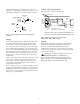
To Wire a Two-Speed Motor: Install and bond pump according to local codes and ordinances; use bonding lug on motor (see Figure 1). Use solid copper conductor No. 8 AWG (8.4mm2) or larger. Wire the pump as shown in the diagram. Ground (Green) BONDING LUG MOTOR NAMEPLATE Low Speed 230 Volt Lines Back of motor with Terminal Board MOTOR CANOPY L2=COM L1=HI A=LOW A GREEN GROUND SCREW L2 Common Power Supply for Optional Timer.
TABLE IA – RECOMMENDED CIRCUIT BREAKER SIZE AND WIRING DATA Model No. AWG (mm2) Wire Gauge Size at 90° C Dist in Ft.
TABLE IA (Continued)– RECOMMENDED CIRCUIT BREAKER SIZE AND WIRING DATA Model No.
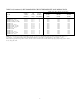
TABLE IA (Continued)– RECOMMENDED CIRCUIT BREAKER SIZE AND WIRING DATA Model No. Voltage/ Hertz (1 Phase) Full Load Amps Branch Circuit Breaker Amp Rating 230 /60 230 /60 230 /60 230 /60 230 /60 230 /60 230 /60 230 /60 230 /60 230 /60 230 /60 230 /60 230 /60 8.5 / 3 8.5 / 3 8.5 / 3 12 / 3.7 12 / 3.7 12 / 3.7 12 / 4.4 12 / 3.7 12 / 3.7 12 / 3.7 12 / 3.7 12 / 3.7 12 / 3.7 15 15 15 15 15 15 15 15 15 15 15 15 15 AWG (mm2) Wire Gauge Size at 90° C Dist in Ft.
OPERATION Do not block pump suction! To do so with body may cause severe or fatal injury. Small children using spa must ALWAYS have close adult supervision! • Tub should have dual suction outlets to prevent body or hair entrapment. • Use only tub suction fittings certified to meet ASME/ANSI standard A112.19.8M-1987. Hazardous suction. Can trap hair or body parts, causing severe injury or death. Too much heat can cause nausea, dizziness, fainting, or death. Do not block suction. Check temperature.
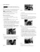
PUMP SERVICE Hazardous voltage. Can shock, burn,or cause death. Disconnect power before working on pump or motor. Pump should only be serviced by qualified personnel. To avoid dangerous or fatal electrical shock hazard, disconnect power to motor before working on pump or motor! No lubrication or regular maintenance are needed. If shaft seal is damaged, repair as follows: Figure 5 Removing Old Seal: Installing New Seal: 1. Disconnect power to pump motor. 2.
STORAGE/WINTERIZING 1. Close all valves on suction and return piping. 2. Remove drain plug in bottom of front plate. To prevent damage to components from fumes, store spa chemicals away from pump and spa. If possible, store chemicals in another room. 3. Drain all piping and storage tanks exposed to freezing temperatures. 4. Be sure no airlocks are holding water in system. Allowing pump to freeze will damage pump and void warranty! 5.
TROUBLESHOOTING GUIDE Read and understand safety and operating instructions in this manual before doing any work on pump! A. PUMP DOES NOT OPERATE 1. Check GFCI for proper operation according to GFCI manufacturer’s instructions. 2. Check for plugged impeller. Follow disassembly/assembly instructions under “Pump Service”, Page 9. 3. Consult dealer/installer or service representative. B. IMPROPER JET ACTION 1. Check for blocked fittings. Blocked fittings will cause poor flow and poor jet action. 2.
REPAIR PARTS LIST DURA-JETTM “DJ” SPA PUMP 1 2 3 4 5 6 10 7 8 9 2478 0596 Key No. 1 2 3 4 5 6 7 8 9 10 • • • • • • • • Description Motor Slinger Seal Plate O-Ring Seal* Impeller Front Plate/Volute Drain Plug Screw, 1/4-20x1-1/2” Nut, Hex 1/4-20, Brass Nameplate Decal, ”For use with pools and spas...” Voltage Label - 230 Volts Voltage Label - 115 Volts Voltage Label - 115/230 V olts Warning Tag Warning Tag Cord Assembly Qty.
Parts are common to all models listed except as noted; Motor (Key No. 1), Impeller (Key No. 6), and Volute (Key No. 7) are listed below. Motor Package (Key No. 1) Impeller (Key No. 6) Volute (Key No.
READ, THEN KEEP THESE INSTRUCTIONS FOR FUTURE REFERENCE *S377* S377 (Rev.