
User guide

Page 6 55862_97_A
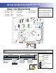
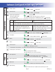
DIP Switches and Jumper Definitions
DIP Switchbank A Key
A1 ............... Test Mode (normally Off)
A2 ............... In “ON” position, add one high-speed pump (or blower) with Heater
A3 ............... In “ON” position, add two high-speed pumps (or 1 HS Pump and Blower) with Heater
A4 ............... In “ON” position, add four high-speed pumps (or 3 HS Pumps and Blower) with Heater
A10 ............... When switched ON when spa is on, system will enter the Edit Menu for Configuration Settings
Do not start spa with A10 turned on or CFE* error will occur
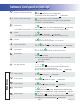
A11 ............... In “ON” position, enables Special Amperage Rule, see "SA" in Software Configuration section for functionality with your system
............... In “OFF” position, disables Special Amperage Rule
A12 ............... Persistent memory reset (used when spa is powering up) See "Persistent Memory and Powering Up" page
A2, A3, and A4 work in combination to determine the number of high-speed devices and blowers that can run before the heat is disabled. i.e.
A2 and A3 in the ON position and A4 in the OFF position will allow the heater to operate with up to 3 high-speed pumps (or two HS Pumps and
Blower) running at the same time. Heat is disabled when the fourth high-speed pump or blower is turned on.
Note: A2/A3/A4 all off = No heat with any high-speed pump or blower.
*CFE errors are illegal configurations such as a pump and a blower set to run on the same output. The configuration must be corrected before
the spa will operate.
Assignable DIP Switch Key
A5 ...... Not Assigned
A6 ...... Not Assigned
A7 ...... Not Assigned
A8 ...... Not Assigned
A9 ...... Not Assigned
B1 ...... Not Assigned
B2 ...... Not Assigned
B3 ...... Not Assigned
B4 ...... Not Assigned
B5 ...... Not Assigned
B6 ...... Not Assigned
B7 ...... Not Assigned
B8 ...... Not Assigned
B9 ...... Not Assigned
B10 ...... Not Assigned
B11 ...... Not Assigned
B12 ...... Not Assigned
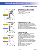
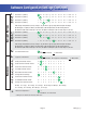
Jumpers Key
J91 .........Jumper on 1 Pin only enables Real Time Clock function, for use with time capable panels.
Jumper on Pins 1 and 2 will disable RTC function, for use with non-time capable panels.
WARNING:
sSetting DIP switches incorrectly may cause abnormal system behavior and/or damage to system components.
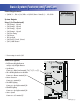
sRefer to Switchbank illustration on Wiring Configuration page for correct settings for this system.
sContact Balboa if you require additional configuration pages added to this hot sheet.