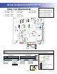
MS8500E Mach 3 Hot Sheet Master Spas System PN 55862 System Model # GL8-MS8500E-RCA-3.0K Software Version # 30 EPN # 2615 Base PCBA – PN 55863 PCB GL8000 – PN 22960 Rev B or C HEX File – 10013930_MS8500E Configuration Signature – E9FC010D Base Panels MP700 – PN 53251-01 Aux Panels AX10 (Jets 1) – PN 52803 AX10 (Jets 2) – PN 52804 AX10 (Jets 4) – PN 52806 Template used: 40598-v29-30_D.pdf 07/19/2007 55862_97_A.
System Revision History System PN EPN 55862 Date Requested By 2615 01.02.
Basic System Features and Functions Power Requirements Internal Reference 53859-04. . . GL8000 Base System 25093 . . . . . PS-34 Pump Splitter s 6!# ^ ! OR ! (Z OR 6!# ,INE TO .
Persistent Memory and Powering Up Any time you change DIP Switches or Software Configuration Settings that affect parameters the user can change (any filter settings, set temperature default, Celsius vs Fahrenheit, 12-hour vs 24-hour time, reminders suppression, etc), you must reset Persistent Memory for your DIP Switch or Software Configuration Settings changes to take effect. You should also reset Persistent Memory after loading a new file into a board (using the ESM, purchased seperately).
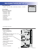
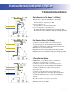
Wiring Configuration and DIP Settings HIPot Testing Note: Setup 1 (As Manufactured) 6 #IRC 0UMP 6 3PA ,IGHT 6 /ZONE 6 !<6 (Stereo) J2 J74 3 2 J75 J76 N K15 K1 G G K10 J60 1 J11 2 1 J38 3 2 1 J37 G N PS-34 A. N V. W1 J14 W2 J16 Spa Light N G F7 J12 G N 2-Spd P2 K2 3 J16 J5 P/N 22960_C 2 F4 G MADE IN U.S.A. F7, T30A 480V 3 J50 BALBOA INSTRUMENTS, INC. GL8000 Mach 3 J10 J77 J54 K5 J53 1 2 J96 3 J52 J47 J7 F2, T 0.
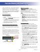
DIP Switches and Jumper Definitions WARNING: sSetting DIP switches incorrectly may cause abnormal system behavior and/or damage to system components. sRefer to Switchbank illustration on Wiring Configuration page for correct settings for this system. sContact Balboa if you require additional configuration pages added to this hot sheet. DIP Switchbank A Key A1 ............... Test Mode (normally Off) A2 ............... In “ON” position, add one high-speed pump (or blower) with Heater A3 ...............
Electrical Service Configuration Options F For Software Configured System Single Service (1 x 16 Amp or 1 x 32 Amp) F2 T 0.5A 250V J95 F2 This option is configured and shipped as the default.
Software Configuration Settings Program Filter Cycles by Duration n Y n = Start and stop times; for time capable panels. Y = Duration; for non-time capable panels = 1 DIP Switch Pump 1 in Filter (w/Circ Pump) n Y (This feature is used in Circ Mode only.) Allows Pump 1 Low to operate in Filter Cycles to add extra filtration.
PUMP SPEEDS Software Configuration Settings Continued Pump 6 Speeds Blower Speeds 0 1 0 = Disabled; 1 = On/Off; 0 1 0 = Disabled; 1 = On/Off; = 1 DIP Switch = 2 DIP Switch LIGHTING CONTROL Separate Spa Light Buttons n Y See Chart Below (This feature applies when n = No Spa light button, Spa Light output is on with Fiber; using Fiber Optic light) Y = Separate Spa Light button on ML900 or Aux panel; = 1 DIP Switch Note: The Light button on an ML900 panel is a SpaLight button.
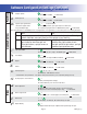
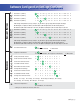
AUXILIARY BUTTONS Software Configuration Settings Continued Aux Button 1 (Bank A) 1 2 3 4 5 6 b g F E o t d P n A U r O H 9 L 8 Aux Button 2 (Bank A) 1 2 3 4 5 6 b g F E o t d P n A U r O H 9 L 8 Aux Button 3 (Bank A) 1 2 3 4 5 6 b g F E o t d P n A U r O H 9 L 8 Aux Button 4 (Bank A) 1 2 3 4 5 6 b g F E o t d P n A U r O H 9 L 8 1-6 = Assigns Pump Number (Pump 1, Pump 2, etc); b = Blower; g = Spa Light; F = Fiber-Optic wheel/light; E = EitherLight; o = Option; t = Mister; d = CK Mode/Cool; P = CK
Software Configuration Settings Continued Default Set Temperature * 5 6 7 8 9 0 1 2 3 4 E F n 5 = 95˚F/35.0˚C; 6 = 96˚F/35.5˚C; 7 = 97˚F/36.0˚C; 8 = 98˚F/36.5˚C; 9 = 99˚F/37.0˚C; 0 = 100˚F/38.0˚C; 1 = 101˚F/38.5˚C; 2 = 102˚F/39.0˚C; 3 = 103˚F/39.5˚C; 4 = 104˚F/40.0˚C; E = 80˚F/26.5˚C; F = 85˚F/29.5˚C n = 90˚F/32.0˚C * Sets default for user preferences - only applies when persistent memory is reset (A12 On) during power-up. Freeze Temperature Threshold 3 4 9 5 3 = 39˚F/3.9˚C; 4 = 44˚F/6.
Filter Default Start Time Set * = 1 DIP Switch * Sets default for user preferences - only applies when persistent memory is reset (A12 On) during power-up. Filter Default Duration Set * 1 2 1 = Set 1; 2 = Set 2; = 1 DIP Switch * Sets default for user preferences - only applies when persistent memory is reset (A12 On) during power-up.
Remote Button 1 (Bank B) 1 2 3 4 5 6 b g F E o t d P n A U r O H 9 L 8 Remote Button 2 (Bank B) 1 2 3 4 5 6 b g F E o t d P n A U r O H 9 L 8 Remote Button 3 (Bank B) 1 2 3 4 5 6 b g F E o t d P n A U r O H 9 L 8 Remote Button 4 (Bank B) 1 2 3 4 5 6 b g F E o t d P n A U r O H 9 L 8 Remote Button 5 (Bank B) 1 2 3 4 5 6 b g F E o t d P n A U r O H 9 L 8 Remote Button 6 (Bank B) 1 2 3 4 5 6 b g F E o t d P n A U r O H 9 L 8 Remote Button 7 (Bank B) 1 2 3 4 5 6 b g F E o t d P n A U r O H 9 L 8 R
ML75X/MX75X SERIES BUTTONS Software Configuration Settings Continued ML75x/MX75x Custom Button 1 1 2 3 4 5 6 b g F E o t d P n A U r O H 9 L 8 ML75x/MX75x Custom Button 2 1 2 3 4 5 6 b g F E o t d P n A U r O H 9 L 8 ML75x/MX75x Custom Button 3 1 2 3 4 5 6 b g F E o t d P n A U r O H 9 L 8 ML75x/MX75x Custom Button 4 1 2 3 4 5 6 b g F E o t d P n A U r O H 9 L 8 ML75x/MX75x Custom Button 5 1 2 3 4 5 6 b g F E o t d P n A U r O H 9 L 8 ML75x/MX75x Custom Button 6 1 2 3 4 5 6 b g F E o t d P n A U
ML55X SERIES BUTTONS Software Configuration Settings Continued ML55x Custom Button 1 1 2 3 4 5 6 b g F E o t d P n A U r O H 9 L 8 ML55x Custom Button 2 1 2 3 4 5 6 b g F E o t d P n A U r O H 9 L 8 ML55x Custom Button 3 1 2 3 4 5 6 b g F E o t d P n A U r O H 9 L 8 ML55x Custom Button 4 1 2 3 4 5 6 b g F E o t d P n A U r O H 9 L 8 ML55x Custom Button 5 1 2 3 4 5 6 b g F E o t d P n A U r O H 9 L 8 1-6 = Assigns Pump Number (Pump 1, Pump 2, etc); b = Blower; g = Spa Light; F = Fiber-Optic wheel/
Software Configuration Settings Continued Special Amperage Rule * 1 2 3 1 = Blower off when 2nd high-speed pump on; 2 = Max 1 high-speed pump 3 = Max 2 high-speed pumps * Note: DIP A11 must be ON to use Special Amperage Rule.
Ozone Connections Note: A special tool is required to remove the pins from the connector body once they are snapped in place. Check with your Balboa Account Manager for information on purchasing a pin-removal tool.
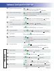
Panel Configurations TIME CAPABLE Note: RTC jumper (J91) on Main PCBA must be OFF (1 pin only) MP700 PN 53251-01 with No Overlay (Customer supplied) s Connects to Main Panel terminal J70, J71, J72, or J73 AUXILIARY Note: Connects to Aux Panel terminal J31, J34, J40, or J16 Blower Jets 1 Blower Jets 1 Blower Jets 1 AX10 (Up to four can be used) Jets 1 - PN 52803 with No Overlay (Customer supplied) Jets 2 - PN 52804 with No Overlay (Customer supplied) Jets 4 - PN 52806 with No Overlay (Customer suppl