
Specifications


9
ELECTRICAL WIRING INSTRUCTIONS
IMPORTANT NOTICE: The electrical wiring of this spa must meet the requirements of the National Electrical Code (NEC)
and any applicable state or local codes. The electrical circuit must be installed by a qualified electrician and approved by a
local building/electrical inspection authority.
1. This spa must be permanently connected (hard-wired) to the power supply. No plug-in connections or extension
cords are to be used in conjunction with the operation of this spa. Supplying power to the spa which is not in
accordance with these instructions will void both the independent testing agency listing and the manufacturer’s
warranty.
2. The power supplied to this spa must be a dedicated circuit with no other appliances or lights sharing the power
provided by the circuit.
3. To determine the current and voltage and wire size required, refer to section “Power Requirements” (Pages 3, 4).
• Wire size must be appropriate per NEC and/or local codes.
• We recommend type THHN wire
• All wiring must be copper to ensure proper connections. Do not use aluminum wire.
• When using wire larger than #6 (10mm2), add a junction box near the spa and reduce to short lengths of #6
(10mm2) wire to connect to spa.
4. The electrical supply for this product must include a suitably rated circuit breaker to open all ungrounded supply
conductors to comply with Section 422-20 of the National Electrical Code, ANSI/NFPA 70. The disconnecting
means shall be accessible, located within sight from spa equipment, and shall be located at least 5 ft (1.52m)
horizontally away from the inside walls of the spa.
5. The electrical circuit supplied for the spa must include a suitable ground fault circuit interrupter (GFCI) as required
by NEC Article 680-42. (GFCI NOT INCLUDED)
6. To gain access to the spa’s power terminal block, remove the screws and cabinet panel on the side of the spa under
the control panel, then remove the two screws from the control pack.
7. Connect wires, color to color, on terminal block. TIGHTEN SECURELY! All wires must be hooked up securely or
damage could result.
8. Secure the control box door panel with screws, and then re-install the cabinet panel under the control panel.
Electrical installation is now completed.
IMPORTANT CANADA SAFETY INSTRUCTIONS
When using this electrical equipment, basic safety precautions should always be followed, including the following.
1. Read and follow all instructions
2. A green colored terminal or terminal marked G, Gr, Ground, Grounding or the ground symbol is located inside
the supply terminal box or compartment. To reduce the risk of electric shock, this terminal must be connected to
the grounding means provided in the electric supply service panel with continuous copper wire equivalent in size
to the circuit conductors that supply this equipment.
3. At least two lugs marked “Bonding Lugs” are provided on the external surface or on the inside of the supply
terminal box/compartment. To reduce the risk of electric shock, connect the local common bonding grid in the
area of the hot tub to these terminals with an insulated or bare copper conductor not smaller than No. 6 AWG.
4. All field-installed metal components such as rails, ladders, drains or other similar hardware within 10 feet (3m) of
the hot t
ub shall be bonded to the equipment grounding buss with copper conductors not smaller than
No. 6 AWG.
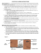
Spa Shell
Spa
Cabinet
Drain Valve
Light
Slide Valves
Control Panel
Radio-CD
Subwoofer
(Speaker)
Cabinet Panel
Figure 5
Control Pack