
Instruction manual

7ML19981FB06 MultiRanger 100/200 – INSTRUCTION MANUAL Page 17
mmmmm
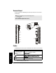
Wiring
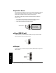
Transducers
A 0.1 µF (100V or greater) capacitor is included with the MultiRanger for retrofitting old
MultiRanger Plus installations. Please see
MultiRanger 100/200 Installation (for
retrofitting MultiRanger Plus Installations)
on page 247.
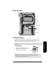
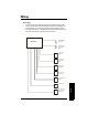
Relays
Relay contacts are shown in the de-energized position. All relays are handled identically
and can be configured as positive or negative logic using P118.
Warning: Hazardous voltage present on transducer terminals during
operation.
Run the transducer cable in a grounded metal conduit, separate from other
wiring (except TS-3 temperature sensor wiring, if applicable).
Notes:
• Do not use coaxial cable because of electrical noise interference
• Do not connect the shield and white transducer wires together; wire to separate
terminals
• Disregard older transducer manuals that recommend these practices
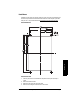
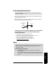
TRANSDUCER TWO
TRANSDUCER ONE
black
white
white
black
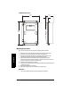
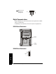
RELAY 1
RELAY 2
RELAY 3
RELAY 4
RELAY 5
RELAY 6
Relay Ratings
• four Form A, NO
relays(1,2,4,5)
• two Form C, NO or
NC relays (3,6)
• 5A at 250Vac, non-
inductive
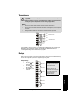
Power Failure
Relays 1, 2, 4, and 5 are
normally open and will fail
in the normal state.
Relays 3 and 6 can be
wired either normally open
or normally closed, and
will fail in their de-
energized states.