
Instruction manual

Page 16 MultiRanger 100/200 – INSTRUCTION MANUAL 7ML19981FB06
mmmmm
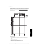
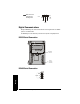
Wiring
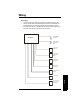
Terminal Board
The terminal board on the MultiRanger allows all inputs and outputs to be connected
simultaneously.
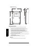
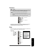
Cables
The MultiRanger transceiver requires a shielded two-wire connection to the transducer.
Note: Recommended torque on terminal clamping screws.
• 0.56 - 0.79 Nm
• 5 - 7 in.lbs
Please do not overtighten the screws.
Connection Cable Type
mA input and mA output
sync, Temperature sensor,
discrete input, dc input
Transducer
2 copper conductors, twisted, with shield
1
/drain wire,
300V 0.324 - 0.823 mm
2
(22 - 18 AWG)
Maximum length: 365 m
1.
Preferred shielding is braided screen.
Do not use a coaxial transducer cable extension with the
MultiRanger. Electrical noise interference affects
performance.
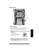
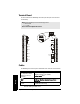
Relay output
AC input
Relay to be copper conductors per local requirements to
meet 250 V 5A contact rating.
L2/N L1
TB1
TB3
TB2
RELAY 1
RELAY 2
RELAY 3
RELAY 4
RELAY 5
RELAY 6
2
1
mA INPUT
SHIELD
SYNC
1
2
4 - 20 m A
OUTPUTS
TS-3
SHIELD
1
2
DISCRETE
INPUTS
RS485
B
A
COM
12-30 V
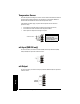
TB1
DC Version