
Instruction manual

7ML19981FB06 MultiRanger 100/200 – INSTRUCTION MANUAL Page 139
mmmmm
Parameters
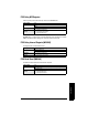
Positive Logic
In software, all relays are programmed the same way, with ON setpoints indicating when
to change the relay contact state (open or closed). This parameter allows the reversal of
the operation so that relay contacts can be NORMALLY CLOSED or NORMALLY OPEN.
P118 is preset to 2 which is positive logic.
Negative Logic
When P118 = 3 (negative logic), the operation for the indexed relay is reversed from
normal.
P119 Relay Logic Test
Forces the relay control logic into an ACTIVATED or DE-ACTIVATED state.
This parameter tests site wiring and control logic programming. Forcing the relay to an
activated or de-activated state is similar to the MultiRanger detecting an event and
responding to it. Helpful in testing new installations and diagnosing control problems.
Pump Setpoint Modifiers (P121 and P122) [MR 200]
Please note that these parameters apply to the MultiRanger 200 only.
These parameters provide alternate ways of starting the pumps in the pump group. See
the
Pump Control
section on page 58 for descriptions of the pump control algorithms.
P121 Pump by Rate [MR 200]
Sets the pump relays to accept control by rate of level change once the first ON setpoint
is reached.
Use this function when multiple pumps are to be controlled by rate of level change rather
than by setpoints.
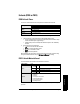
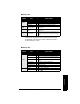
Primary Index Relay
Values
0 * OFF - Control from MultiRanger algorithms
1 Activate relay control
2 De-activate relay control
Related
• P111 Relay Control Function
• P910 Toggle Relays
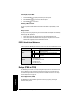
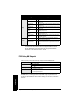
Primary Index
Single Point Model Dual Point Model
Transducer Level
Values
0 * OFF (pump by level)
1ON (pump by rate)
Related
•P007 Span
• P111 Relay Control Function
•P132 Pump Start Delay
• Rate (P700 to P708)