© The Chamberlain Group, Inc. A DUCHOSSOIS ENTERPRISE 845 Larch Avenue, Elmhurst, Illinois 60126 As of date of manufacture, meets all ANSI/UL 325 Safety Standards ® and requirements for residential and commercial applications.
CONTENTS PAGE CONTENTS A review of safety alert symbols ..............................2 You'll need tools ......................................................3 Illustration of door installation .................................4 Opener carton inventory ..........................................5 Hardware inventory .................................................5 PAGE Safety reversing sensor information ....................16 Install the safety reversing sensor ..................
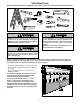
You'll Need Tools During assembly, installation and adjustment of the opener, instructions will call for hand tools shown below. Pencil Carpenter's Level 1 Hack Saw 2 Tape Measure Wire Cutters Claw Hammer Drill 3/16", 5/16" and 5/32" Drill Bits Stepladder Pliers Screwdriver 1/2" and 7/16" Sockets and Wrench WARNING Adjustable End Wrench CAUTION To avoid damage to the garage door and opener, disable locks before installing and operating the opener.
Before you begin, survey your garage area. Do any of the following conditions apply to you? Horizontal and vertical reinforcement is needed for lightweight garage doors (fiberglass, steel, aluminum, door with glass panels, etc.). See page 19 for details. FINISHED CEILING Support bracket & fastening hardware is required. See page 12. Slack in chain tension is normal when garage door is closed.
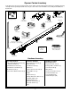
Opener Carton Inventory Your garage door opener is packaged in two cartons which contain all parts illustrated below. If anything is missing, carefully check the packing material. Parts may be "stuck" in the foam. Hardware for assembly and installation is listed below.
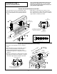
Assembly Section: Pages 6 – 7 Assembly Step 1 WARNING Attach the Rail to the Opener Use only those screws mounted in the top of the opener. Any other screws will cause serious damage to the opener. O • Place the opener on packing material to protect the cover. • Remove the (2) 5/16"-18x1/2" washered screws mounted in the top of the opener. • Align rail at an angle with opener so one hole in rail and opener line up. • Thread one of the washered screws part way in.
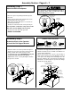
Assembly Step 3 Tighten the Chain Outer Nut Lock Washer Inner Nut • Spin the inner nut and lock washer down the threaded shaft, away from the trolley. • To tighten the chain, turn outer nut in the direction shown. As you turn the nut, keep the chain from twisting. • When the chain is approximately 1/2" above the base of the rail at its midpoint, re-tighten the inner nut to secure the adjustment. Sprocket noise can result if chain is either too loose or too tight.
Installation Section: Pages 8 – 20 Installation Step 1 WARNING Determine Header Bracket Location If the header bracket is not rigidly fastened to a structural support on the header wall or ceiling, the safety reverse system may not work properly (see page 23). The door might not reverse when required, and could cause serious injury or death. The garage door springs, cables, pulleys, brackets and their hardware are under extreme tension. Do not attempt to loosen, move or adjust them yourself.
You can attach the header bracket either to the wall above the garage door, or to the ceiling. Follow the instructions which will work best for your particular requirements. Installation Step 2 Install the Header Bracket Fasten the Header Bracket to the Wall • Center the bracket on the vertical guideline with • Mark either set of bracket holes (do not use the the bottom edge of the bracket on the horizontal holes designated for ceiling mount).
Installation Step 3 Attach the Rail to the Header Bracket • Position the opener on the garage floor below the header bracket. Use packing material as a protective base. If the door spring is in the way you'll need help. Have someone hold the opener securely on a temporary support to allow the rail to clear the spring. • Position the chain pulley bracket against the header bracket. • Align the bracket holes and join with a clevis pin as shown. • Insert a ring fastener to secure.
Installation Step 4 CAUTION Position the Opener To prevent damage to steel, aluminum, fiberglass or glass panel doors, do not rest the opener on the door without using a 2x4. You will need help at this point if the ladder is not tall enough. • Open the door all the way and place a 2x4 laid flat on the top section beneath the rail. A 2x4 laid flat is convenient for setting an ideal door-to-rail distance. • Raise the opener onto a stepladder.
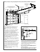
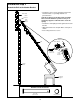
Installation Step 5 WARNING Hang the Opener The opener could fall and injure someone if it is not properly secured. Fasten the opener securely to structural supports of the garage. Two representative installations are shown. Yours may be different. Hanging brackets should be angled, Figure 1, to provide rigid support. On finished ceilings, Figure 2, attach a sturdy metal bracket to structural supports in ceiling before installing the opener. The bracket and fastening hardware are not supplied.
Installation Step 6 WARNING Install the Door Control Children operating or playing with a garage door opener can injure themselves or others. The garage door could close and cause serious injury or death. Install the Door Control (or any additional push buttons) out of the reach of children and away from all moving parts of the door and door hardware, but where the garage door is visible. Do not allow children to operate the push button(s) or the remote control transmitter(s).
Installation Step 7 Install the Light 75 Watt Max. Light Bulb Install the Light • Install a 75 watt maximum light bulb in the socket. The light will turn ON and remain lit for approximately 4-1/2 minutes when power is connected. Then the light will turn OFF. • If the bulb burns out prematurely due to vibration, replace with a "Garage Door Opener" bulb. Opener Installation Step 8 WARNING Attach the Manual Release Rope and Handle Do not use the red handle to pull the door open or closed.
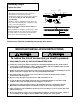
Installation Step 9 WARNING Electrical Requirements To prevent electrocution or fire, installation and wiring must be in compliance with local electrical and building codes. To reduce the risk of electric shock, your garage door opener has a grounding type plug with a third grounding pin. This plug will only fit into a grounding type outlet. If the plug doesn't fit into the outlet you have, contact a qualified electrician to install the proper outlet. Right Wrong • Do not change the plug in any way.
Information you'll need before you begin the installation of the safety reversing sensor. The safety reversing sensor must be connected and aligned correctly before the garage door opener will move in the down direction. This is a required safety device and cannot be disabled. WARNING Without a properly working safety reversing sensor, persons (particularly children) could be killed by a closing garage door. Read and follow all instructions.
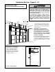
Figure 2 Installation Step 10 Garage WALL or DOOR TRACK Installation Mounting Bracket With Square Holes Install the Safety Reversing Sensor (Receiving and Sending Eyes) "C" Wrap Figures 2, 3 and 4 show recommended assembly of bracket(s) and "C" wrap based on the wall installation of the sensors on each side of the garage door as shown on page 16, or on the garage door tracks themselves. Figure 5 shows variations which may fit your installation requirements better.
• Insert the wire connector into each sensor and push until you hear a click (Figure 6). The white tab on the sensor should be flush with the back of the connector.
Installation Step 11 CAUTION Fasten Door Bracket & Plate To prevent damage to steel, aluminum, fiberglass or glass panel doors, always reinforce the inside of the door both vertically and horizontally with an angle iron. A horizontal brace should be long enough to be secured to 2 vertical supports. A vertical brace should cover the height of the top panel. The illustration shows one piece of angle iron as the horizontal brace.
Installation Step 12 Connect Door Arm to Trolley Make sure garage door is fully closed. Pull the manual release handle to disconnect the outer trolley from the inner trolley. Slide the outer trolley back (away from the door) about 2” as shown in Figures 1, 2 and 3. Figure 1: • Fasten straight door arm section to outer trolley with a clevis pin. Secure the connection with a ring fastener. • Fasten curved section to the door bracket in the same way as shown. Figure 2: • Bring arm sections together.
Adjustment Section: Pages 21 – 23 Adjustment Step 1 WARNING Adjust the UP and DOWN Limits Improper adjustment of the travel limits could interfere with the proper operation of the safety reverse system. See page 23. The door might not reverse when required and could seriously injure or kill someone under it. Limit adjustment settings regulate the points at which the door will stop when moving up or down. The door will stop in the up direction if anything interferes with door travel.
Adjustment Step 2 WARNING Adjust the Force Too much force on the door will interfere with the proper operation of the safety reverse system. See page 23. The door might not reverse properly when required and could seriously injure or kill someone under it. Do not increase the force beyond what is required to close the door. Do not use the force adjustments to compensate for a binding or sticking garage door. Force adjustment controls are located on the back panel of the opener.
Adjustment Step 3 WARNING Test The Safety Reversing Sensor Without a properly working safety reversing sensor, persons (particularly children) could be seriously injured or killed by a closing garage door. Repeat this test once a month. • Press the Door Control push button to open the door. • Place the opener carton in the path of the door. • Press the Door Control push button to close the door. The door will not move more than an inch, and the opener light(s) will flash.
IMPORTANT SAFETY INSTRUCTIONS WARNING WARNING To reduce the risk of severe injury or death to persons: 1. READ AND FOLLOW ALL INSTRUCTIONS. 2. Do not permit children either to operate or to play with the opener. Keep a remote control in a location inaccessible to children. 3. Operate opener only when the door is in full view and free from any obstruction. Keep the door in sight until it is completely closed. NO ONE SHOULD CROSS THE PATH OF THE MOVING DOOR. 4. Check safety reversal system monthly.
Operation of Your Opener WARNING Weak or broken springs could allow an open door to fall (either rapidly or unexpectedly), resulting in serious injury, death or property damage. If possible, use the manual release rope and handle only when the door is fully closed. Activate the opener with any of the following devices: 1. The Door Control. Hold push button down until the door starts to move. 2. A Remote Control Transmitter. Hold push button down until the door starts to move. 3.
Having a Problem? Situation Probable Cause & Solution The opener doesn't operate from either the Door Control or a remote control: 1. Have you disabled all door locks? Review installation instruction warnings on page 7. 2. Does the opener have electric power? Plug a lamp into the outlet. If it doesn't light, check the fuse box or the circuit breaker. (Some outlets are controlled by a wall switch.) 3. Repeated operation may have tripped the overload protector in the motor. Wait 15 minutes. Try again. 4.
Having a Problem? (continued) Situation Probable Cause & Solution The door opens but won't close: 1. Check the safety reversing sensor. If the sensor lights do not glow, see page 18. The door reverses for no apparent reason and opener light doesn't blink: 1. Is something obstructing the door? Pull the red manual release handle. Operate the door manually. If it is unbalanced or binding, call a garage door serviceman to correct the problem. 2.
Repair Parts Rail Assembly Parts 3 1 4 E AS RE IL G 3A4 8 . NO RA 2 5 KEY NO. PART NO. DESCRIPTION 1 2 3 4 1A995 41A2780 41A3489 CD1008 CD1010 CD1012 83A4 Master link kit Chain pulley bracket Complete trolley assembly 8 Foot Rail Assembly 10 Foot Rail Assembly 12 Foot Rail Assembly Rail grease 5 Installation Parts 3 2 1 6 5 4 NLY TO UN NG MO LI CEI UP NOT ICE KEY NO. 1 2 3 4 5 6 7 PART NO.
Repair Parts Opener Assembly Parts 1 2 3 4 15 18 7 18 17 15 (Down) Contact 5 12 14 LIMIT SWITCH ASSY. 8 9 16 6 10 13 Brown Wire DN Grey Wire UP Drive Gear Center Limit Contact KEY NO. PART NO. 1 2 3 41D4478 144B18 41C4470 4 41A2817 5 6 7 8 9 143D146 175B88M 30B432 12A461 41A3150 (Up) Contact Yellow Wire 11 DESCRIPTION Rail support bracket assembly kit Pulley (Chain) Gear and sprocket assy.
Accessories Available for your Opener Model 1702 Outside Quick Release: Required for a garage with NO access door. Model 81LM "Smart" Remote Control: Includes visor clip. Model 60 Outside Keylock: Opens the garage door automatically from outside when remote control is not handy. Model 61LM Single-Function Standard Size Remote Control: Includes visor clip. Model CD1008 8 foot Complete Rail and Chain Assembly: To allow an 8 foot door to open fully.
Index Access Door/Outside Quick Release Accessory................................................................................................4 Chain Tension ....................................................................................................................................................4, 7 Electrical Safety Warnings........................................................................................................................
LIFT-MASTER SERVICE IS ON CALL OUR LARGE SERVICE ORGANIZATION SPANS AMERICA HOW TO ORDER REPAIR PARTS Selling prices will be furnished on request or parts will be shipped at prevailing prices and you will be billed accordingly. WHEN ORDERING REPAIR PARTS, ALWAYS GIVE THE FOLLOWING INFORMATION: INSTALLATION AND SERVICE INFORMATION IS AS NEAR AS YOUR TELEPHONE SIX DAYS A WEEK. SIMPLY DIAL OUR TOLL FREE NUMBER: • PART NUMBER • PART NAME • MODEL NUMBER 1-800-528-9131 HOURS: 7:00 A.M. TO 3:30 P.M.