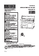
8:00 a.m. - 8:00 p.m., EST, Monday - Friday.
Grill Operation 1-2-3 Before Grilling: Step 1 Step 2 Step 3 Keep your grill a safe distance away from your property.* Always perform a leak test.* Keep children away from the grill. During Grilling: (To avoid tripping safety valves, please follow these instructions carefully!) Step 1 Step 2 Step 3 First open lid and turn gas tank on slowly. Turn only one knob on at a time when lighting the grill. Use protective gloves when grill gets hot.
TABLE OF CONTENTS Safety Information…………………………………….………...….……………………….……..….4 Package Contents…..………………..…..….……...…...................………………………………..6 Hardware Contents……………………………………………………………….……………………7 Preparation…..………………..…………………….……...….……………………………………….7 Assembly Instructions……………………..……………….……………………………………...…8 Natural Gas Conversion…………………………………………….............................................14 Operation Instructions…………………………………...……………….…………………..…...20 Care and Maintenance……………………………….
SAFETY INFORMATION Please read and understand this entire manual before attempting to assemble, operate or install the product. If you have any questions regarding the product, please call customer service at 1-800-963-0211, 8:00 a.m. - 8:00 p.m., EST, Monday - Friday 1. The installation of this appliance must conform with local codes or, in the absence of local codes, with either the National Fuel Gas Code, ANSI Z223.1-2015/NFPA 54-2015, or Natural Gas and Propane Installation Code, CSA/CGA-B149.1-2015. 2.
SAFETY INFORMATION 17. Do not store a spare LP-gas cylinder under or near this appliance. 18. Never fill the cylinder beyond 80 percent full. 19. If the information in “17” and “18” is not followed exactly, a fire causing death or serious injury may occur. 20. The outdoor cooking gas appliance must be isolated from the gas supply piping system by closing its individual manual shutoff valve during any pressure testing of the gas supply system at test pressures equal to or less than 1/2 psi (3.5 KPa). 21.
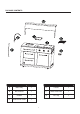
PACKAGE CONTENTS PART DESCRIPTION QUANTITY PART DESCRIPTION QUANTITY A Main Body 1 E Faucet 1 B Bar Counter 1 F Water Inlet Hose 1 C Griddle 1 G Fat Tray 1 D Side Burner Grate 1 6
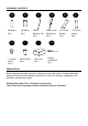
HARDWARE CONTENTS AA BB CC DD AA Battery Qty. 1 9V Battery Qty. 1 Orifice Removal Tool Qty. 1 Phillips Head Screwdriver Qty. 1 HH II JJ KK 1.45mm Orifice Qty. 3 M6x15 Screw Qty. 4 Grill Cover Qty. 1 EE 23 x 24 mm Wrench Qty. 1 FF 17 x 19 mm Wrench Qty. 1 Slotted Screwdriver Qty. 1 PREPARATION Before beginning assembly of product, make sure all parts are present. Compare parts with package contents list and hardware contents list.
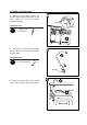
ASSEMBLY INSTRUCTIONS 1ˊ Remove all the packing material from inside and outside the grill. 2ˊ Lift the bar counter (B) carefully and insert the 2 legs into the square holes located at the back of the main body (A). B 3ˊ Once the bar counter (B) is fully inserted into the main body (A), secure the parts together with 4 M6 x 15 screws (II) using the Phillips screwdriver (DD).
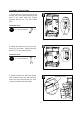
ASSEMBLY INSTRUCTIONS 4ˊ Remove the 2 screws securing the access panel located at the back of the main body (A) with the Phillips screwdriver (DD). Screw Hardware Used DD Phillips Head Screwdriver Access Panel x1 5ˊ Using the 23 x 24 mm wrench (EE), remove the hex nut from the faucet (E) and set aside. Hardware Used EE 23 x 24 mm Wrench x1 Hex Nut 6. Insert the faucet (E) into the round hole on the surface of the main body (A).
ASSEMBLY INSTRUCTIONS 7. Screw the hex nut onto the faucet (E) through the access panel opening at the back of the main body (A). Tighten securely with the 23 x 24 mm wrench (EE). Hardware Used EE 23 x 24 mm Wrench x1 Hex Nut 8. Attach the water inlet hose (F) to the faucet (E) as shown. Tighten securely with the 17 x 19 mm wrench (FF). Hardware Used FF 17 x 19 mm Wrench x1 9. Pull the drawers out. Press the drawer slide release levers. One side will push down, the other side pull push up.
ASSEMBLY INSTRUCTIONS 10. Feed the water inlet hose (F) and the drain hoses though either set of access holes in either the side panel or back panel of the main body (A). Drain Hose 11. Reinstall the 2 drawers to the original positions. 12. Reinstall the screws with the Phillips Head Screwdriver (DD) to secure the access panel at the back of main body (A).
ASSEMBLY INSTRUCTIONS 16. Place the fat tray (G) in the main body (A). 17. Your grill is now assembled.
NATURAL GAS CONVERSION PREPARATION: IMPORTANT: The 10 ft. Natural Gas Hose is NOT INCLUDED with the product. 10 ft. Natural Gas Hose Before beginning conversion, make sure all parts are present. Compare parts with package contents. If any part is missing or damaged, do not attempt to convert. Contact customer service for replacement parts. 1. Turn off gas supply, and then remove cap on gas supply side. 2. Recommended: Install a shut-off valve on gas supply side before installing the socket. 3.
NATURAL GAS CONVERSION IMPORTANT: After your outdoor kitchen is converted to natural gas, the working pressure for natural gas is 7 in. water column (WC). Gas pressure is affected by gas line size and the length of gas line run from house. Follow the recommendations in the chart below. From House to Grill Tubing Size 3/8 in. DIA 1/2 in. DIA 2/3 in. of run 3/4 in. 51 – 100 ft. 1/3 in. of run 1/2 in. Over 101 ft. 3/4 in. DIA Distance Up to 25 ft. 26 – 50 ft.
NATURAL GAS CONVERSION CONVERSION INSTRUCTION: Before the conversion, make sure all control knobs are in the OFF position, LP tank valve is closed, and tank is disconnected from regulator and removed from grill. 18. Open the side burner lids and remove the griddle and grate. On the left hand side, remove the R-pin at the back of the main burner to detach it from bracket and then take the burner out.
NATURAL GAS CONVERSION 21. Remove the LP orifices of the main burners and the side burners with the orifice removal tool (CC) and install the 1.45mm orifice (HH). 21 Hardware Used CC HH Orifice Removal Tool x1 1.45mm Orifice x3 22. Re-install the side burners. Make sure the orifices are aligned with the burners and the ignition pins are installed in their original positions. Check for sparks before operating your grill. 22 23.
NATURAL GAS CONVERSION 24. Remove the 3 main burner control knobs by grasping and pulling out. Insert the supplied slotted screwdriver (KK) into the hole of each main burner control valve stem as shown. Rotate the stem counterclockwise (to the left) as far as it will go. The stem will now be set in the NG position. Reattach the control knobs. 24.1 Hardware Used 24.2 KK Slotted screwdriver x1 25 25. Use the 17 x 19 mm wrench (FF) to remove the LP hose and regulator from the manifold.
NATURAL GAS CONVERSION WARNING: Please remember this is an outdoor gas grill. Many areas of the grill generate extreme heat. We have taken every precaution to protect you from the contact areas. However, it is impossible to isolate all high-temperature areas. Therefore, use good judgment and a certain degree of caution when grilling on this product. We suggest a covered, protected hand during operation of the grill. Do not move the grill when it is in operation or hot to the touch.
OPERATING INSTRUCTIONS Never attach an unregulated gas line to the appliance. Connection to an unregulated gas line can cause excessive heat or fire. Verify the type of gas supply to be used, either Natural Gas (N.G.) or Liquid Propane (L.P.), and make sure the serial plate agrees with that of the supply. Conversion kits are available separately for an additional cost which will enable you to convert your grill from L.P. to N.G. or to convert your grill from N.G. to L.P.
OPERATING INSTRUCTIONS L.P. GAS INSTALLATION Gas grills that are set to operate with L.P. gas come with a high capacity hose and regulator assembly. (Note: Only use the pressure regulator and hose assembly supplied with the grill or a replacement pressure regulator and hose assembly specified by the manufacture). This assembly is designed to connect directly to a standard 20 lb. L.P. cylinder. L.P. cylinders are not included with the grill. L.P.
OPERATING INSTRUCTIONS 7. Open the tank valve fully. Use a soapy water solution to check all connections for leaks before attempting to light your grill. See “Pre Operation Leak Testing" on page 24. If a leak is found, turn the tank valve off and do not use your grill until the leak is repaired. As shown in Fig. 6a gas tank must be place vertically. It is unsafe to operate the grill if the gas tank is not vertical as shown in Fig. 6b. Fig. 6a Fig. 6b WARNING: The Type I connective coupling (see Fig.
OPERATING INSTRUCTIONS L.P. TANK INFORMATION Never use a dented or rusted L.P. tank or cylinder with a damaged valve. L.P. cylinders are equipped with an O.P.D. (Overfilling Prevention Device). The device shuts off the flow of gas to a cylinder after 80% capacity is reached. This limits the potential for release of gas when the cylinder is heated, averting a fire or possible injury. The L.P. cylinder must have a shut-off valve terminating in an L.P.
OPERATING INSTRUCTIONS PRE OPREATION LEAK TESTING Although all gas connections on the grill are leak tested prior to shipment, a complete gas tightness check must be performed at the installation site due to possible shifting during shipment, installation or excessive pressure unknowingly being applied to the unit. Periodically check the whole system for leaks and immediately check the system if the smell of gas is detected. 1. Do not smoke while leak testing. 2. Extinguish all open flames. 3.
OPERATING INSTRUCTIONS Clearance to combustible construction - A minimum of 24 in. from the sides and back must be maintained from the gas grill above and below the cooking surface to adjacent vertical combustible construction. Clearance to non-combustible construction - A minimum of 10 in. clearance from the back of the grill to non-combustible construction is required for the lid to fully open.
OPERATING INSTRUCTIONS BEFORE AND AFTER LIGHTING 1. Ensure your grill is located on a level surface. 2. Keep the gas grill area clean and free from combustible materials, gasoline, and other flammable vapors and liquids. 3. Ensure nothing is obstructing the flow of combustion and ventilation air. 4. Ensure the ventilation of the cylinder enclosure are free and clear of debris. 5. Visually check burner flames. WARNING Check the gas supply line for cuts, wear or abrasion.
OPERATING INSTRUCTIONS GRILL BURNER LIGHTING Warning: Do not lean over grill when lighting. Turn off LP supply at cylinder when appliance is not in use. Main Burner & Side Burner Lighting Illustration: 1. Check that the control knobs are in the OFF position. 2. Open valve at tank fully by turning counterclockwise. 3. Open lid during lighting. 4. Push the Electronic Ignition down 3 to 4 seconds while turning the GRILL or SIDE BURNER control knob to the HIGH position. The burner should ignite.
CARE AND MAINTENANCE GENERAL CLEANING IMPORTANT: Before cleaning, make sure all controls are off and the grill is cool. Always follow label instructions on cleaning products. For routine cleaning, wash with soap and water using a soft cloth or sponge. Rinse with clean water and dry at once with a soft, lint-free cloth to avoid spots and streaks. To avoid scratching the surface, do not use steel wool to clean the grill. Use vinyl grill cover to protect finish from weather.
CARE AND MAINTENANCE GENERAL MAINTENANCE - Keep outdoor cooking gas appliance area clear and free from combustible materials, gasoline and other flammable vapors and liquids. - Do not obstruct the flow of combustion and ventilation air. - Keep the ventilation openings of the cylinder enclosure free and clear from debris. - Visually check the burners.
TROUBLESHOOTING Many solutions given here can make your grilling experience safer and more enjoyable. You can also call customer service department at 1-800-963-0211, 8:00 a.m. - 8:00 p.m., EST, Monday Monday - Friday. PROBLEM Grill or side cooker will not light. Burner flame is yellow and gas odor can be smelled. POSSIBLE CAUSE 1. The ignition wire came off the electrical igniter/valve. 2. The distance between the ignition pin and the burner is greater than 5/32 in. - 3/16 in. (side burner). 3.
TROUBLESHOOTING PROBLEM CORRECTIVE ACTION 1. This model is set for 7 in. natural gas usage. Please check your natural gas supply system to have correct gas pressure. Regulator is not needed for NG model. Low heat 1. Low heat is found in natural Check the orifice if you installed NG with the knob gas models. nozzles. Conversion kit provides the 2. Ports are blocked. in “HIGH” following nozzles: 3. LP tank has run out. position. Burner Orifice Size Main Burner 1.45mm Side Burner 1.45mm 2.
8:00 a.m. - 8:00 p.m., EST, Monday - Friday.
EXPLODED VIEW For replacement parts, call our customer service department at 1-800-963-0211, 8:00 a.m. - 8:00 p.m., EST, Monday - Friday.
REPLACEMENT PARTS LIST PART DESCRIPTION Rear Counter Assembly QUANTITY Sink Support Long 2 6 9A 11 13 Sink Support Short Ignition Pin Left Rear Panel Left Side Cart Panel 2 1 1 1 2 15 Glide Support 2 Glide 6 17 Door Handle Cart Crossbeam Badge Switch Handle Base Regulator Ignition Pole Assembly Knob Bezel Base Panel Assembly Castor 3 1 1 1 8 1 1 3 1 2 19 21 23 25A 27 28C 30 32 34 36 37 Glide Stop 1 38 39 41 43 45 Cylinder Tray Assembly Heat Shield Left Door Support Firebox Support 1
entre 8 h et 20 h (HNE), du lundi au vendredi.
Fonctionnement du gril 1-2-3 Grill Operation 1-2-3 Avant Befored’utiliser Grilling:le gril : eWDSH Step 1 eWDSH Step 2 eWDSH Step 3 3ODFHU OH JULO j XQH GLVWDQFH VpFXULWDLUH GH YRWUH SURSULpWp Keep your grill a safe distance away from your property.* 7RXMRXUV HIIHFWXHU XQ HVVDL G¶pWDQFKpLWp perform a leak test.* Always 7HQLU OHV HQIDQWV j O¶pFDUW GX JULO Keep children away from the grill.
TABLE DES MATIÈRES Renseignements sur la sécurité .............................................................................................. 38 Contenu de la boîte ................................................................................................................... 40 Matériel ....................................................................................................................................... 41 Préparation..................................................................
RENSEIGNEMENTS SUR LA SÉCURITÉ Veuillez lire et prendre connaissance de ce manuel en entire avant de tenter d’assembler, d’utiliser ou d’installer le produit. Si vous avez des questions au sujet du produit, veuillez téléphoner au service à la clientèle au 1 800 963-0211, entre 8 h et 20 h (HNE), du lundi au vendredi. 1. L’installation de cet appareil doit être conforme aux codes locaux ou, en l’absence de codes locaux, au National Fuel Gas Code, (ANSI Z223.
RENSEIGNEMENTS SUR LA SÉCURITÉ 16. La bouteille utilisée doit être munie d’un collier qui protège la valve. 17. Ne pas entreposer de bouteille de propane liquide de rechange en dessous ou près de cet appareil. 18. Ne jamais remplir la bouteille au-delà de 80 pour cent de sa capacité. 19. Si les renseignements contenus aux points «17» et «18» ne sont pas respectés à la lettre, il y a 19. risqué d’incendie pouvant causer des blessures graves ou meme la mort. 20.
CONTENU DE LA BOÎTE PIÈCE DESCRIPTION QUANTITÉ PIÈCE DESCRIPTION QUANTITÉ A Module principal 1 E Robinet 1 B Comptoir de bar 1 F Tuyau pour prise d’eau 1 C Plaque chauffante 1 G Grille du brûleur latéral 1 Plateau à à graisse 1 D 40
MATÉRIEL AA BB Pile AA Qté. 1 Pile 9 V Qté. 1 HH II JJ Vis M6x15 Qty. 4 Couvre-gril Qté. 1 Orifice de combustion de ĭ1,45 mm Qty. 3 CC DD Clé de changement d’orifices Qté. 1 Tournevis à tête cruciforme Qté. 1 EE Clé de 23 x 24 mm Qté. 1 FF Clé de 17 x 19 mm Qté. 1 KK Tournevis à tête plate Qté. 1 PRÉPARATION Avant de commencer l’assemblage du produit, s’assurer que toutes les pièces sont incluses. Comparer les pièces avec la liste des pièces et la liste des outils.
INSTRUCTIONS D’ASSEMBLAGE 5 HWLUHU WRXW OH PDWpULHO G¶HPEDOODJH j O¶LQWpULHXU HW j O¶H[WpULHXU GX JULO / HYHU OH FRPSWRLU GH EDU % DYHF SUpFDXWLRQ HW LQVpUHU OHV SDWWHV GDQV OHV WURXV FDUUpV VLWXpV j O¶DUULqUH GX PRGXOH SULQFLSDO $ B / RUVTXH OH FRPSWRLU GH EDU % HVW HQWLqUHPHQW LQVpUp GDQV OH PRGXOH SULQFLSDO $ ¿[HU OHV SLqFHV HQVHPEOH DYHF YLV 0 [ ,, j O¶DLGH GX WRXUQHYLV j WrWH FUXFLIRUPH '' II Matériel utilisé II DD A 9LV 0 [ M6 x 15 Screw
INSTRUCTIONS D’ASSEMBLAGE ASSEMBLY INSTRUCTIONS 4ˊ 5HWLUHU OHV YLV VXU OH SDQQHDX G¶DFFqV Remove the 2 screws securing the VLWXp j O¶DUULqUH GX PRGXOH SULQFLSDO $ j access panel located at the back of the O¶DLGH GX WRXUQHYLV j WrWH FUXFLIRUPH '' main body (A) with the Phillips screwdriver (DD).
INSTRUCTIONS D’ASSEMBLAGE ASSEMBLY INSTRUCTIONS 7. 9Screw LVVHU O¶pFURX KH[DJRQDO VXU OH URELQHW the hex nut onto the faucet (E)( HQ SDVVDQW SDU O¶RXYHUWXUH GX SDQQHDX through the access panel opening at the G¶DFFqV VLWXp j O¶DUULqUH GX PRGXOH SULQFLSDO back of the main body (A). Tighten $ 6HUUHU DYHF OD FOp GH [ PP (( securely with the 23 x 24 mm wrench (EE).
INSTRUCTIONS D’ASSEMBLAGE ,QWURGXLUH OH WX\DX G¶DUULYpH G¶HDX ) HW OH WX\DX GH YLGDQJH GDQV OHV WURXV G¶DFFqV GX SDQQHDX ODWpUDO RX GX SDQQHDX DUULqUH GX PRGXOH SULQFLSDO $ Tuyau de vidange Drain Hose 11. Réinstaller les 2 tiroirs dans leur position originale.
INSTRUCTIONS D’ASSEMBLAGE ASSEMBLY INSTRUCTIONS GDQV OH 16. 3ODFHU OH SODWHDX j JUDLVVH Place the fat tray (G) in *the main PRGXOH SULQFLSDO $ body (A). 17. 9RWUH JULO HVW PDLQWHQDQW DVVHPEOp Your grill is now assembled.
CONVERSION AU GAZ NATUREL NATURAL GAS CONVERSION PREPARATION: IMPORTANT: IMPORTANT /H WX\DX GH JD] QDWXUHO GH P Q¶HVW PAS INCLUS DYHF FH SURGXLW The 10 ft. Natural Gas Hose is NOT INCLUDED with the product. Tuyau de gaz 10 ft.
CONVERSION AU GAZ NATUREL IMPORTANT : $SUqV DYRLU FRQYHUWL YRWUH FXLVLQH H[WpULHXUH DX JD] QDWXUHO OD SUHVVLRQ GH IRQFWLRQQHPHQW SRXU OH JD] QDWXUHO HVW FP GH FRORQQH G¶HDX &( /D SUHVVLRQ GX JD] HVW DIIHFWpH SDU OD WDLOOH GH OD FRQGXLWH GH JD] HW OD ORQJXHXU GH OD FRQGXLWH GH JD] j SDUWLU GH OD PDLVRQ 6XLYUH OHV UHFRPPDQGDWLRQV GX WDEOHDX FL GHVVRXV De la maison jusqu’au gril Distance Taille du tuyau -XVTX¶j P FP GH GLDPqWUH P FP GH GLDPqWUH P P
CONVERSION GAZ NATUREL NATURAL GASAU CONVERSION INSTRUCTIONS DE CONVERSION : CONVERSION INSTRUCTION: $YDQW OD FRQYHUVLRQ V¶DVVXUHU TXH WRXV OHV ERXWRQV GH FRPPDQGH VRQW HQ SRVLWLRQ G¶DUUrW TXH OD YDOYH GH OD ERXWHLOOH GH SURSDQH OLTXLGH HVW IHUPpH HW TXH OD ERXWHLOOH HVW GpEUDQFKpH Before the conversion, make sure all control knobs are in the OFF position, LP tank valve is du régulateur et retirée du gril. closed, and tank is disconnected from regulator and removed from grill.
CONVERSION AU GAZ NATUREL 5HWLUHU OHV RUL¿FHV GH FRPEXVWLRQ GH SURSDQH OLTXLGH GX EUOHXU SULQFLSDO HW GHV EUOHXUV ODWpUDX[ DYHF OD FOp GH FKDQJHPHQW G¶RUL¿FHV && HW LQVWDOOHU OHV RUL¿FHV GH FRPEXVWLRQ GH ĭ PP ++ 21 Matériel utilisé CC HH Clé de Orifice FKDQJHPHQW Removal Tool G¶RUL¿FHV x1 2UL¿FH GH Orifice 1.
CONVERSION AU GAZ NATUREL 24. Retirez les 3 boutons de commande du brûleur principal en les agrippant et en les tirant. Insérez le tournevis à tête plate fourni (KK) dans le trou de chaque tige de robinet de commande du brûleur principal, tel qu’il est illustré. Faites tourner la tige dans le sens contraire des aiguilles d’une montre (vers la gauche) jusqu’à ce qu’elle se bloque. La tige est maintenant à la position « NG » (gaz naturel). Remettez les boutons de commande en place. 24.1 24.
CONVERSION AU GAZ NATUREL AVERTISSEMENT: Veuillez noter que ceci est un gril au gaz extérieur. Plusieurs zones du gril génèrent une chaleur extrême. Nous avons pris toutes les precautions pour vous protéger des zones de contact. Malheureusement, il est impossible d’isoler toutes les zones à haute temperature. Veuillez faire appel à votre jugement et faire prevue d’une certaine prudence lorsque vous utilisez ce produit. Nous vous suggérons de couvrir et de protéger vos mains lorsque vous utilisez ce gril.
MODE D’EMPLOI 1H MDPDLV ¿[HU XQH FRQGXLWH GH JD] QRQ UpJOHPHQWpH j FHW DSSDUHLO /D FRQQH[LRQ j XQH conduite de gaz non réglementée peut causer une chaleur excessive ou un incendie.
MODE D’EMPLOI INSTALLATION DE GAZ P.L.
MODE D’EMPLOI OPERATING INSTRUCTIONS 2 XYULU FRPSOqWHPHQW OD YDOYH GH OD ERXWHLOOH 8WLOLVHU XQH VROXWLRQ G¶HDX VDYRQQHXVH SRXU 7. GpWHFWHU OD SUpVHQFH GH IXLWHV DX QLYHDX GHV EUDQFKHPHQWV DYDQW GH WHQWHU G¶DOOXPHU OH JULO Open the tank valve fully. Use a soapy water solution to check all connections for leaks 9RLU © (VVDL G¶pWDQFKpLWp DYDQW XWLOLVDWLRQ ª j OD SDJH 6¶LO \ D XQH IXLWH IHUPHU OD YDOYH GH before attempting to light your grill. See “Pre Operation Leak Testing" on page 24.
MODE D’EMPLOI INFORMATION SUR LA BOUTEILLE DE PROPANE LIQUIDE 1H MDPDLV XWLOLVHU XQH ERXWHLOOH GH SURSDQH OLTXLGH URXLOOpH ERVVHOpH RX DYHF XQH YDOYH HQGRPPDJpH /HV ERXWHLOOHV GH 3 / VRQW PXQLHV G¶XQ GLVSRVLWLI GH SUpYHQWLRQ GH UHPSOLVVDJH H[FHVVLI &H GLVSRVLWLI DUUrWH OH ÀX[ GH JD] YHUV OD ERXWHLOOH ORUVTX¶HOOH HVW UHPSOLH j GH VD FDSDFLWp &HFL OLPLWH OH SRWHQWLHO GH GpJDJHPHQW GH JD] TXDQG OD ERXWHLOOH HVW FKDXIIpH pYLWDQW DLQVL OHV LQFHQGLHV HW OHV EOHVVXUHV pYHQWXHOOHV /D ERXWHLOOH GH 3 /
MODE D’EMPLOI OPERATING INSTRUCTIONS ESSAI D’ÉTANCHÉITÉ AVANT UTILISATION PRE OPREATION LEAK TESTING Although all gas connections on the grill are leak tested prior to shipment, a complete gas 0rPH VL WRXV OHV EUDQFKHPHQWV GH JD] VXU OH JULO VRQW WHVWpV SRXU OHV IXLWHV DYDQW G¶rWUH H[SpGLpV XQH YpUL¿FDWLRQ FRPSOqWH GH O¶pWDQFKpLWp DX JD] GRLW rWUH HQWUHSULVH VXU OH VLWH GH O¶LQVWDOODWLRQ HQ UDLVRQ tightness check must be performed at the installation site due to possible shifting during G¶XQ GpSODFHPHQW
MODE D’EMPLOI (VSDFH OLEUH HW FRQVWUXFWLRQ LQÀDPPDEOH ,O GRLW \ DYRLU XQ HVSDFHPHQW PLQLPXP GH FP GH FKDTXH F{Wp HW j O¶DUULqUH GX JULO DX GHVVXV HW HQ GHVVRXV GH OD VXUIDFH GH FXLVVRQ HQWUH O¶DSSDUHLO HW WRXWH FRQVWUXFWLRQ LQÀDPPDEOH YHUWLFDOH DGMDFHQWH (VSDFH OLEUH HW FRQVWUXFWLRQ QRQ LQÀDPPDEOH ,O GRLW \ DYRLU XQ HVSDFHPHQW PLQLPXP GH FP HQWUH OH JULO HW WRXWH FRQVWUXFWLRQ QRQ LQÀDPPDEOH j O¶DUULqUH GX JULO SRXU TXH OH FRXYHUFOH SXLVVH V¶RXYULU FRPSOqWHPHQW /¶HQWUHSRVDJH G¶XQ DSSDU
MODE D’EMPLOI AVANT ET APRÈS LE DÉMARRAGE 6¶DVVXUHU TXH OH JULO HVW SODFp VXU XQH VXUIDFH SODQH *DUGHU OD ]RQH GX JULO SURSUH HW ORLQ GH PDWpULDX[ FRPEXVWLEOHV G¶HVVHQFH HW G¶DXWUHV YDSHXUV HW OLTXLGHV LQÀDPPDEOHV 6¶DVVXUHU TXH ULHQ Q¶REVWUXH OH ÀX[ GH FRPEXVWLRQ HW GH YHQWLODWLRQ G¶DLU 6¶DVVXUHU TXH O¶HQFHLQWH GH OD ERXWHLOOH HVW YHQWLOpH HW H[HPSWH GH GpEULV 9pUL¿HU YLVXHOOHPHQW OHV ÀDPPHV GHV EUOHXUV AVERTISSEMENT 9pUL¿H] OD FRQGXLWH G¶DOLPHQWDWLRQ HQ JD] SRXU YRLU V
MODE D’EMPLOI ALLUMAGE DES BRÛLEURS DU GRIL Avertissement : Ne pas se pencher au-dessus du gril lors de l’allumage. Couper l’alimentation en P.L. de la bouteille lorsque l’appareil n’est pas utilisé. Illustration de l’allumage des brûleur principal at latéraux: 1. Vérifier que les boutons de commande sont à OFF. 2. Ouvrir la valve de la bouteille complètement en la tournant dans le sens antihoraire. 3. Ouvrir le couvercle durant l’allumage. 4.
NETTOYAGE ET ENTRETIEN NETTOYAGE GÉNÉRAL ,03257$17 $YDQW GH QHWWR\HU V¶DVVXUHU TXH WRXV OHV ERXWRQV VRQW j OD SRVLWLRQ 2)) HW TXH OH JULO HVW UHIURLGL 7RXMRXUV VXLYUH OHV LQVWUXFWLRQV IRXUQLHV VXU OHV pWLTXHWWHV GH SURGXLWV GH QHWWR\DJH 3RXU OH QHWWR\DJH GH URXWLQH QHWWR\HU DYHF GH O¶HDX VDYRQQHXVH HW XQ OLQJH GRX[ RX XQH pSRQJH 5LQFHU DYHF GH O¶HDX SURSUH HW VpFKHU DYHF XQ OLQJH GRX[ VDQV SHOXFKHV SRXU pYLWHU OHV WDFKHV HW OHV WUDFHV 3RXU pYLWHU G¶pJUDWLJQHU OD VXUIDFH QH SDV XWLOLVHU GH ODLQH
NETTOYAGE ET ENTRETIEN CUIDADO Y MAINTENANCE MANTENIMIENTO CARE AND ENTRETIEN GÉNÉRAL GENERAL MAINTENANCE outdoor cooking gas appliance area clear and free from combustible materials, gasoline -*Keep DUGHU O¶HQGURLW R VH WURXYH O¶DSSDUHLO GH FXLVVRQ j JD] H[WpULHXU ORLQ GH PDWpULDX[ FRPEXVWLEOHV G¶HVVHQFH HW G¶DXWUHV YDSHXUV HW OLTXLGHV LQÀDPPDEOHV and other flammable vapors and liquids.
DÉPANNAGE Plusieurs solutions fournies ici peuvent render votre expérience de gril plus sécuritaire et agréable. Vous pouvez aussi appeler notre département du service à la clientèle au 1 800 963-0211, entre 8 h et 20 h (HNE), du lundi au vendredi. PROBLÉME Le brûleur principal ou les brûleurs latétaux ne s’allument pas. La flamme du brûleur est jaune et il y a une odeur de gaz. Embrasement excessif. Un brûleur Ne fonctionne plus. CAUSES POSSIBLES MESURES CORRECTIVES 1.
DÉPANNAGE PROBLÈME CAUSES POSSIBLES MESURES CORRECTIVES lorsque le en position est vide. gaz propane liquide. attendre 5 minutes. rapides dans la pression peuvent De la maison au gril gaz naturel. du panneau 2.
entre 8 h et 20 h (HNE), du lundi au vendredi.
VUE ÉCLATÉE Pour obtenir des pièces de remplacement, appeler notre department du service à la clientèle au 1 800 963-0211, entre 8 h et 20 h (HNE), du lundi au vendredi.
LISTE DES PIÈCES DE RECHANGE PIÈCE 1 3 5 7A 10 DESCRIPTION Arrière de comptoir Comptoir en granit principal Évier avec égouttoir Assemblage de chambre de combustion latérale Panneau de milieu de chariot QUANTITÉ PIÈCE DESCRIPTION Arrière d¶assemblage de comptoir QUANTITÉ 1 2 1 4 Support d¶évier long 2 1 6 Support d¶évier court 2 1 9A 7LJH G¶DOOXPDJH 1 1 11 Panneau arrière gauche Panneau de chariot gauche 1 1 12 Petit Panneau arriere 1 13 14 Câble de soutien du panneau de contrô
de lunes a viernes de 8:00 a.m. a 8:00 p.m., hora estándar del Este.
Operación deOperation la parrilla en tres pasos Grill 1-2-3 Antes utilizar la parrilla: Beforede Grilling: 3DVR Step 1 3DVR Step 2 3DVR Step 3 0DQWHQJD OD SDUULOOD D XQD GLVWDQFLD SUXGHQWH GH VX FDVD Keep your grill a safe distance away from your property.* 6LHPSUH UHDOLFH XQD SUXHED GH IXJD Always perform a leak test.* 0DQWHQJD D ORV QLxRV DOHMDGRV GH OD SDUULOOD Keep children away from the grill.
ÍNDICE Información de seguridad......................................................................................................... 72 Contenido del paquete.............................................................................................................. 74 Aditamentos............................................................................................................................... 75 Preparación....................................................................................
INFORMACIÓN DE SEGURIDAD Lea y comprenda completamente este manual antes de intentar ensamblar, usar o instalar el producto. Si tiene preguntas relacionadas con el producto, llame al Departamento de Servicio al Cliente al 1-800-963-0211, de lunes a viernes de 8:00 a.m. a 8:00 p.m., hora estándar del este. 1. La instalación de este electrodoméstico debe cumplir con los códigos locales o, en su defecto, con el Código Nacional de Gas Combustible, ANSI Z223.
INFORMACIÓN DE SEGURIDAD 16. El cilindro utilizado debe incluir un anillo para proteger la válvula del mismo. 17. No almacene un tanque de gas PL de reserva debajo o cerca de este electrodoméstico. 18. Nunca llene el cilindro más allá del 80% de su capacidad. 19. Si no sigue con precisión la información detallada en los puntos “17” y “18”, se podría producir un 19. incendio y causar lesiones graves o la muerte. 20.
CONTENIDO DEL PAQUETE PIEZA DESCRIPCIÓN CANTIDAD PIEZA DESCRIPCIÓN CANTIDAD A Cuerpo principal 1 E Grifo 1 B Cubierta del bar 1 F Manguera de entrada de agua 1 C Plancha 1 G Rejilla del quemador lateral 1 Bandeja para la grasa 1 D 74
CONTENIDO DEL PAQUETE AA Batería AA Cant. 1 HH ĭ Orificio de 1,45 mm Cant. 3 BB Batería de 9 voltios Cant. 1 II Tornillo M6x15 Qty. 4 CC DD Herramienta para eliminar orificios Cant. 1 Destornillador phillips Cant. 1 JJ EE Llave inglesa de 23 x 24 mm Cant. 1 FF Llave inglesa de 17 x 19 mm Cant. 1 KK Cubierta para parrilla Cant. 1 Destornillad or ranurado Cant. 1 PREPARACIÓN Antes de comenzar a ensamblar el producto, asegúrese de tener todas las piezas.
INSTRUCCIONES DE ENSAMBLAJE 1.
INSTRUCCIONES DE ENSAMBLAJE ASSEMBLY INSTRUCTIONS 4.4ˊ Retire los 2the tornillos que aseguran Remove 2 screws securing el the SDQHO GH DFFHVR XELFDGRV HQ OD SDUWH access panel located at the back of the SRVWHULRU GHO FXHUSR SULQFLSDO $ FRQ HO main body (A) with the Phillips GHVWRUQLOODGRU 3KLOOLSV '' screwdriver (DD).
INSTRUCCIONES DE ENSAMBLAJE ASSEMBLY INSTRUCTIONS 7. (Screw QURVTXH OD WXHUFD KH[DJRQDO HQ HO JULIR the hex nut onto the faucet (E) ( SRU OD DSHUWXUD GHO SDQHO GH DFFHVR HQ OD through the access panel opening at the SDUWH SRVWHULRU GHO FXHUSR SULQFLSDO $SULHWH back of the main body (A). Tighten ¿UPHPHQWH FRQ OD OODYH GH [ PP (( securely with the 23 x 24 mm wrench (EE).
INSTRUCCIONES DE ENSAMBLAJE 10.
INSTRUCCIONES DE ENSAMBLAJE ASSEMBLY INSTRUCTIONS * 16. &RORTXH OD EDQGHMD SDUD OD JUDVD Place the fat tray (G) in the main HQ HO FXHUSR SULQFLSDO $ body (A). X SDUULOOD \D HVWi HQVDPEODGD 17. 6Your grill is now assembled.
CONVERSIÓN A GAS NATURAL NATURAL GAS CONVERSION PREPARATION: IMPORTANT: IMPORTANTE La manguera de 3,05 parais gas NO SEwith INCLUYE FRQ HO The 10 ft. Natural Gas m Hose NOTnatural INCLUDED the product. SURGXFWR Manguera 10 ft.
CONVERSIÓN A GAS NATURAL IMPORTANTE: 'HVSXpV GH FRQYHUWLU OD FRFLQD SDUD H[WHULRUHV D JDV QDWXUDO OD SUHVLyQ GH WUDEDMR SDUD JDV QDWXUDO HV GH FP GH FROXPQD GH DJXD & $ /D SUHVLyQ GH JDV VH YH DIHFWDGD SRU HO WDPDxR \ HO ODUJR GH OD OtQHD GH JDV SURYHQLHQWH GH OD FDVD 6LJD ODV UHFRPHQGDFLRQHV GHO VLJXLHQWH FXDGUR Desde la casa hasta la parrilla Distancia Tamaño de las tuberías +DVWD P FP GH GLiP P ± P FP GH GLiP ± P FP D FP
CONVERSIÓN GAS NATURAL NATURAL GASACONVERSION INSTRUCCIONES DE CONVERSIÓN: CONVERSION INSTRUCTION: $QWHV GH UHDOL]DU OD FRQYHUVLyQ DVHJ~UHVH GH TXH WRGDV ODV SHULOODV GH FRQWURO VH HQFXHQWUHQ HQ OD SRVLFLyQ ³2))´ $3$*$'2 Before the conversion, make sure TXH OD YiOYXOD GHO WDQTXH GH 3/ HVWp FHUUDGD \ TXH HO all control knobs are in the OFF position, LP tank valve is WDQTXH HVWp GHVFRQHFWDGR GHO UHJXODGRU \ DOHMDGR GH OD SDUULOOD closed, and tank is disconnected from regulator and removed from grill.
CONVERSIÓN A CONVERSION GAS NATURAL NATURAL GAS HWLUH ORV RUL¿FLRV SDUD 3/ GH 21.5Remove the LP orifices of the main ORV TXHPDGRUHV SULQFLSDOHV \ ORV burners and the side burners with the TXHPDGRUHV ODWHUDOHV FRQ OD KHUUDPLHQWD orifice removal tool (CC) and the SDUD HOLPLQDU RUL¿FLRV && install H LQVWDOH HO 1.45mm orifice (HH). ++ RUL¿FLR GH ĭ PP 21 Aditamentos utilizados Hardware Used CC +HUUDPLHQWD Orifice para eliminar Removal Tool RUL¿FLRV x1 HH ĭ2UL¿FLR GH 1.
CONVERSIÓN A GAS NATURAL 24. Retire las 3 perillas de control del quemador principal sujetándolas y jalándolas. Inserte el destornillador ranurado provisto (KK) en el orificio de cada vástago de válvula de control del quemador principal como se muestra. Gire el vástago en dirección contraria a las manecillas del reloj (hacia la izquierda) hasta el punto máximo. El vástago ahora estará en la posición NG. Vuelva a colocar las perillas de control. 24.1 24.
CONVERSIÓN A GAS NATURAL ADVERTENCIA: recuerde que esta es una parrilla a gas para exteriores. Muchas áreas de la parrilla generan calor extremo. Hemos tomado todas las precauciones a fin de protegerlo de las áreas de contacto. Sin embargo, es imposible aislar todas las áreas de alta temperatura. Por lo tanto, use el sentido común y tenga cierto grado de precaución cuando ase en este producto. Sugerimos que se cubra y proteja las manos cuando opere la parrilla.
INSTRUCCIONES DE FUNCIONAMIENTO Nunca conecte una línea de gas no regulado al electrodoméstico. La conexión a una línea de gas no regulado puede causar calor excesivo o un incendio.
INSTRUCCIONES DE FUNCIONAMIENTO INSTALACIÓN DE GAS PROPANO LÍQUIDO /DV SDUULOODV D JDV TXH HVWiQ FRQ¿JXUDGDV SDUD RSHUDU FRQ JDV SURSDQR OtTXLGR YLHQHQ FRQ XQD PDQJXHUD \ XQ UHJXODGRU GH DOWD FDSDFLGDG (Nota: use solo el juego de manguera y regulador TXH YLHQH FRQ OD SDUULOOD R XQR GH UHSXHVWR HVSHFL¿FDGR SRU HO IDEULFDQWH (VWH MXHJR HVWi GLVHxDGR SDUD FRQHFWDUVH GLUHFWDPHQWH D XQ WDQTXH GH SURSDQR OtTXLGR HVWiQGDU GH NJ /RV WDQTXHV GH SURSDQR OtTXLGR QR VH LQFOX\HQ FRQ OD SDUULOOD SHUR VH SXHG
INSTRUCCIONES DE FUNCIONAMIENTO OPERATING INSTRUCTIONS $EUD SRU FRPSOHWR OD YiOYXOD GHO WDQTXH 8VH XQD VROXFLyQ GH DJXD \ MDEyQ SDUD UHYLVDU WRGDV 7. ODV FRQH[LRQHV SDUD GHWHFWDU IXJDV DQWHV GH LQWHQWDU HQFHQGHU OD SDUULOOD &RQVXOWH ³3UXHED Open the tank valve fully. Use a soapy water solution to check all connections for leaks GH IXJDV SUHYLD D OD RSHUDFLyQ´ HQ OD SiJLQD 6L VH GHVFXEUH XQD IXJD OOHYH OD YiOYXOD GHO before attempting to light your grill.
INSTRUCCIONES DE FUNCIONAMIENTO INFORMACIÓN DEL TANQUE DE GAS P.L.
INSTRUCCIONES DE FUNCIONAMIENTO OPERATING INSTRUCTIONS PRUEBA DE FUGAS ANTES DE LA OPERACIÓN PRE OPREATION LEAK TESTING Although all gas connections on the grill are leak tested prior to shipment, a complete gas $XQTXH VH UHDOL]DQ SUXHEDV GH IXJD D WRGDV ODV FRQH[LRQHV GH JDV GH OD SDUULOOD DQWHV GHO HQYtR GHEH HIHFWXDUVH XQD YHUL¿FDFLyQ FRPSOHWD GHO KHUPHWLVPR GHO JDV HQ HO VLWLR GH OD LQVWDODFLyQ GHELGR tightness check must be performed at the installation site due to possible shifting during D OD SRVL
INSTRUCCIONES DE FUNCIONAMIENTO Aunque se realizan pruebas de fuga a todas las conexiones de gas de la parrilla antes del envío, debe efectuarse una verificación completa del hermetismo del gas en el sitio de la instalación debido a al posible manipulación indebida durante el envoi, instalación o a una presión excesiva que se haya aplicado inconscientemente sobre la unidad. Si en algún momento percibe olor a gas, verifique inmediatamente todo el sistema para detactar fugas.
INSTRUCCIONES DE FUNCIONAMIENTO ANTES Y DESPUÉS DEL ENCENDIDO $VHJ~UHVH GH TXH OD SDULOOD HVWp FRORFDGD VREUH XQD VXSHU¿FLH QLYHODGD 0DQWHQJD HO iUHD GH OD SDUULOOD D JDV GHVSHMDGD \ OLEUH GH PDWHULDOHV FRPEXVWLEOHV JDVROLQD \ RWURV YDSRUHV R OtTXLGRV LQÀDPDEOHV $VHJ~UHVH GH TXH QDGD REVWUX\D HO ÀXMR GHO DLUH GH FRPEXVWLyQ QL GH YHQWLODFLyQ $VHJ~UHVH GH TXH OD YHQWLODFLyQ GHO FRPSDUWLPLHQWR GHO FLOLQGUR HVWp GHVSHMDGD \ OLEUH GH GHVHFKRV 5HDOLFH XQD UHYLVLyQ YLVXDO GH ODV
INSTRUCCIONES DE FUNCIONAMIENTO ENCENDIDO DEL QUEMADOR DE LA PARRILLA Advertencia: no se incline sobre la parrilla al encenderla. Ilustración del encendido del quemador principal y lateral 1. Verifique que las perillas de control estén en la posición OFF(APAGADO). 2. Abra completamente la válvula del tanque girándola en dirección contraria a las manecillas del reloj. 3. Abra la tapa durante el encendido. 4.
CUIDADO Y MANTENIMIENTO LIMPIEZA GENERAL ,03257$17( aQWHV GH OLPSLDU DVHJ~UHVH GH TXH WRGRV ORV FRQWUROHV HVWpQ GHVFRQHFWDGRV \ GH TXH OD SDUULOOD HVWp IUtD 6LHPSUH VLJD ODV LQVWUXFFLRQHV HQ ORV SURGXFWRV GH OLPSLH]D 3DUD OD OLPSLH]D GH UXWLQD ODYH FRQ DJXD \ MDEyQ XVDQGR XQ SDxR VXDYH R HVSRQMD (QMXDJXH FRQ DJXD OLPSLD \ VHTXH FRQ XQ SDxR VXDYH \ VLQ SHOXVDV SDUD HYLWDU PDQFKDV \ YHWDV 3DUD HYLWDU UD\DU OD VXSHU¿FLH QR XVH HVWURSDMRV GH PHWDO SDUD OLPSLDU OD SDUULOOD 8VH XQD FXELHUWD GH YLQLOR S
CUIDADO Y MAINTENANCE MANTENIMIENTO CARE AND LIMPIEZA GENERALGENERAL MAINTENANCE outdoor cooking gas appliance area clear and free from combustible materials, gasoline -1Keep R GHEH KDEHU PDWHULDOHV FRPEXVWLEOHV JDVROLQD QL RWURV YDSRUHV R OtTXLGRV LQÀDPDEOHV FHUFD GH OD ]RQD GRQGH HVWi HO HOHFWURGRPpVWLFR SDUD FRFFLyQ D JDV SDUD H[WHULRUHV and other flammable vapors and liquids.
SOLUCIÓN DE PROBLEMAS Muchas de las soluciones ofrecidas aquí le permitirán usar la parrilla de manera más segura y agradable. También puede llamar a nuestro Departamento de Servicio al Cliente al 1-800-963-0211, de lunes a viernes de 8:00 a.m. a 8:00 p.m., hora estándar del este. PROBLEMA La parrilla no la cocina lateral no encienden. CAUSA POSIBLE 1. El cable de encendido se desconectó del encendedor eléctrico/válvula. 2.
SOLUCIÓN DE PROBLEMAS PROBLEMA La parrilla JHQHUD SRFR FDORU FRQ OD perilla en la SRVLFLyQ ³+,*+´ $/72 CAUSA POSIBLE SOLUCÍON 1. Los modelos a gas natural JHQHUDQ SRFR FDORU /RV SXHUWRV HVWiQ EORTXHDGRV (O WDQTXH GH 3/ VH KD DJRWDGR (VWH PRGHOR HVWi FRQ¿JXUDGR SDUD XWLOL]DU FP GH JDV QDWXUDO 9HUL¿TXH VX VLVWHPD GH VXPLQLVWUR GH gas natural para determinar si tiene una SUHVLyQ GH JDV FRUUHFWD /RV PRGHORV D gas natural no requieren regulador.
de lunes a viernes de 8:00 a.m. a 8:00 p.m., hora estándar del Este.
VISTA DESPIEZADA Para obtener piezas de repuesto, llame a nuestro Departamento de Servicio al Cliente al 1-800-963-0211, de lunes a viernes de 8:00 a.m. a 8:00 p.m., hora estándar del este.
LISTA DE PIEZAS DE REPUESTO PIEZA 1 3 DESCRIPCIÓN Cubierta posterior de granito Cubierta principal de granito CANTIDAD PIEZA 1 2 1 4 5 Fregadero con desague 1 6 7A Cámara de combustión lateral 1 9A 10 Panel central del carrito 1 11 1 13 2 15 12 14 Panel lateral posterior del carrito Cable de soporte del panel de control DESCRIPCIÓN Estructura de la cubierta posterior Soporte large del fregadero Soporte corto del fregadero Pasador de encendido Panel posterior izquierdo Panel lateral