NOTE: Please make all indicated changes before printing. 8:00 a.m. - 8:00 p.m., EST, Monday - Friday.
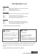
Grill Operation 1-2-3 Before Grilling: Step 1 Step 2 Step 3 Keep your grill a safe distance away from your property.* Always perform a leak test.* Keep children away from the grill. During Grilling: (To avoid tripping safety valves, please follow these instructions carefully!) Step 1 Step 2 Step 3 First open lid and turn gas tank on slowly. Turn only one knob on at a time when lighting the grill. Use protective gloves when grill gets hot.
TABLE OF CONTENTS Safety Information…………………………………….………...….………….………….….………4 Package Contents…..………………..…..….……...…...................………………………………..6 Hardware Contents……………………………………………………………….……………………7 Preparation…..………………..…………………..….……………………………………………..….7 Assembly Instructions……………………..……………….………………………………………...8 Natural Gas Conversion…………………………………………….............................................12 Operating Instructions…………………………….……...…………………………....................19 Care and Maintenance……………………………….
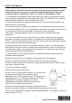
SAFETY INFORMATION Please read and understand this entire manual before attempting to assemble, operate or install the product. If you have any questions regarding the product, please call customer service at 1-800-963-0211, 8:00 a.m. to 8:00 p.m., EST, Monday - Friday. 1. The installation of this appliance must conform with local codes or, in the absence of local codes, with either the National Fuel Gas Code, ANSI Z223.1-2015/NFPA 54-2015, or Natural Gas and Propane Installation Code, CSA/CGA-B149.1-2015.
SAFETY INFORMATION 16. The cylinder used must include a collar to protect the cylinder valve. 17. Do not store a spare LP-gas cylinder under or near this appliance. 18. Never fill the cylinder beyond 80 percent full. 19. If the information in ‘‘17’’ and ‘‘18’’ is not followed exactly, a fire causing death or serious injury may occur. 20.
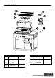
PACKAGE CONTENTS G PART DESCRIPTION QUANTITY PART DESCRIPTION QUANTITY A Main Body 1 E Flame Tamer 3 B Warming Rack 1 F Trash Bin 1 C Grid 3 G Small Knob 1 D Drip Tray 1 6
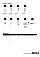
HARDWARE CONTENTS AA BB CC DD AA Battery Qty. 1 9V Battery Qty. 1 Orifice Removal Tool Qty. 1 FF GG HH 1.45mm Orifice Qty. 3 17 x 19 mm Wrench Qty. 1 1.30mm Orifice Qty. 1 Phillips Screwdriver Qty. 1 II Grill Cover Qty. 1 JJ Slotted Screwdriver Qty. 1 PREPARATION Before beginning assembly of product, make sure all parts are present. Compare parts with package contents list and hardware contents list. If any part is missing or damaged, do not attempt to assemble the product.
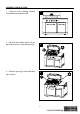
ASSEMBLY INSTRUCTIONS 1. Remove all the packing material from inside and outside the grill. 1 2. Place all three flame tamers (E) on top of each burner on the main body (A). 2 3. Place the grids (C) on the main body (A) as shown.
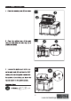
ASSEMBLY INSTRUCTIONS 7. Open the cabinet door of the main body 7 (A) and place the 9V battery (BB) for the control panel light as shown. Hardware Used 9V Battery x1 8 G 8. Screw the small knob (G) into place on the knob bezel on the main body (A). 9. Open the trash bin door of the main body (A) and place the trash bin (F) in position as shown.
ASSEMBLY INSTRUCTIONS 10. Your grill is now assembled.
NATURAL GAS CONVERSION PREPARATION: IMPORTANT: The 10 ft. Natural Gas Hose is NOT INCLUDED. 10 ft. Natural Gas Hose Before beginning conversion, make sure all parts are present. Compare parts with package contents. If any part is missing or damaged, do not attempt to convert. Contact customer service for replacement parts. 1. Turn off gas supply and then remove cap on gas supply side. 2. Recommended: Install a shut-off valve on gas supply side before installing the socket. 3.
NATURAL GAS CONVERSION IMPORTANT: After your grill is converted to natural gas, the working pressure for natural gas is 7 in. water column (WC). Gas pressure is affected by gas line size and the length of gas line run from house. Follow the recommendations in the chart below. From House to Grill Distance Tubing Size Up to 25 ft. 3/8 in. DIA 26 – 50 ft. 1/2 in. DIA 2/3 in. of run 3/4 in. 51 – 100 ft. 1/3 in. of run 1/2 in. More than 101 ft. 3/4 in. DIA WARNING: Place the grill on a flat, level surface.
NATURAL GAS CONVERSION CONVERSION INSTRUCTIONS: Before the conversion, make sure all control knobs are in the OFF position, LP tank valve is closed, and tank is disconnected from regulator and removed from grill. 1. Before the conversion, make sure all control knobs are in the OFF position, LP tank valve is closed, and tank is disconnected from regulator and removed from grill. Next, open lid and remove warming rack, grids and flame tamer. 1 2.
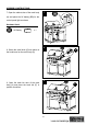
NATURAL GAS CONVERSION 3. Adjust the air shutters of the main burners by loosening the air shutter screws with the Phillips screwdriver (DD). 3 Hardware Used DD Phillips Screwdriver x1 4 4. Remove the LP orifices of all the main burners with the orifice removal tool (CC) and install the1.45mm orifices (FF). CC Hardware Used CC FF Orifice Removal Tool x1 1.45mm Orifice x3 FF 5. Remove the 6 screws at the back of burner box with the Phillips screwdriver (DD).
NATURAL GAS CONVERSION 6. Use the 17 x 19 mm wrench (GG) to remove the hex nut securing the rotisserie burner orifice and hose assembly. Detach the assembly from the bracket. Remove the LP orifice of the rotisserie burner with the orifice removal tool (CC) and install the 1.30mm orifice (HH). Reinstall the orifice and hose assembly and the rear panel as stated in Step 5. 6 GG HH Hardware Used GG 17 x 19 mm Wrench CC Orifice Removal Tool HH 1.30mm Orifice x1 x1 x1 7. Re-install the burners.
NATURAL GAS CONVERSION 9. Remove the 3 main burner control knobs 9.1 by grasping and pulling out. Insert the supplied slotted screwdriver (JJ) into the hole of each main burner control valve stem as shown. Rotate the stem counterclockwise (to the left) as far as it will go. The stem will now be set in the NG position. Reattach the control knobs. 9.2 Hardware Used JJ Slotted screwdriver x1 10. Use the 17 x 19 mm wrench (GG) to remove the LP hose and regulator from the manifold.
NATURAL GAS CONVERSION WARNING: Please remember this is an outdoor gas grill. Many areas of the grill generate extreme heat. We have taken every precaution to protect you from the contact areas. However, it is impossible to isolate all high-temperature areas. Therefore, use good judgment and a certain degree of caution when grilling on this product. We suggest a covered, protected hand during operation of the grill. Do not move the grill when it is in operation or hot to the touch.
OPERATING INSTRUCTIONS Never attach an unregulated gas line to the appliance. Connection to an unregulated gas line can cause excessive heat or fire. Verify the type of gas supply to be used, either Natural Gas (N.G.) or Liquid Propane (L.P.), and make sure the serial plate agrees with that of the supply. Conversion kits are available separately for an additional cost which will enable you to convert your grill from L.P. to N.G. or to convert your grill from N.G. to L.P.
OPERATING INSTRUCTIONS L.P. GAS INSTALLATION Gas grills that are set to operate with L.P. gas come with a high capacity hose and regulator assembly. (Note: Only use the pressure regulator and hose assembly supplied with the grill or a replacement pressure regulator and hose assembly specified by the manufacturer). This assembly is designed to connect directly to a standard 20 lb. L.P. cylinder. L.P. cylinders are not included with the grill. L.P.
OPERATING INSTRUCTIONS 6. Connect the hose and regulator assembly to the tank valve (See Fig. 5). Hand tighten the quick coupling nut clockwise to a full stop. DO NOT use a wrench to tighten because it could damage the quick coupling nut and result in a hazardous condition. Fig. 5 7. Open the tank valve fully counterclockwise. Use a soapy water solution to check all connections for leaks before attempting to light your grill. See “Pre-operation Leak Testing" on page 23.
OPERATING INSTRUCTIONS Disconnecting A Liquid Propane Gas (LP Gas) Tank From Your Grill: 1. Turn the burner knobs and LP gas tank valve to the full OFF position. (Turn clockwise to close.) Fig. 8 2. Detach the hose and regulator assembly from the LP gas tank valve by turning the quick coupling nut counterclockwise. See Fig. 8. CAUTION: When the appliance is not in use, the gas must be turned off at the supply tank. L.P. TANK INFORMATION Never use a dented or rusted L.P.
OPERATING INSTRUCTIONS • The regulator and hose assembly must be inspected before each use of the grill. If there is excessive abrasion or wear or if the hose is cut, it must be replaced prior to the grill being used again. • Cylinders must be stored outdoors out of the reach of children and must not be stored in a building, garage or any other enclosed area. • Only a qualified gas supplier should refill the L.P. tank. • Place dust cap on cylinder valve outlet whenever the cylinder is not in use.
OPERATING INSTRUCTIONS WARNING When leak testing this appliance, make sure to test and tighten all loose connections. A slight leak in the system can result in a low flame or hazardous condition. Most L.P. gas tanks now come equipped with a leak detector mechanism internal to the tank. When gas is allowed to escape rapidly, it shuts off the gas supply. A leak may significantly reduce the gas flow, making the grill difficult to light or causing low flames.
OPERATING INSTRUCTIONS BEFORE AND AFTER LIGHTING 1. Ensure your grill is located on a level surface. 2. Keep the gas grill area clean and free from combustible materials, gasoline, and other flammable vapors and liquids. 3. Ensure nothing is obstructing the flow of combustion and ventilation air. 4. Ensure the ventilation of the cylinder enclosure is free and clear of debris. 5. Visually check burner flames. WARNING Check the gas supply line for cuts, wear or abrasion.
OPERATING INSTRUCTIONS GRILL BURNER LIGHTING Warning: Do not lean over grill when lighting. Turn off LP supply at cylinder when appliance is not in use. Main Burner Lighting Illustration: 1. Check that the control knobs are in the OFF position. 2. Open valve at tank fully by turning counterclockwise. 3. Open lid during lighting. 4. Push the Electronic Ignition down 3 to 4 seconds while turning the GRILL control knob to the HIGH position. The burner should ignite.
OPERATING INSTRUCTIONS If ignition does not take place within 5 seconds, immediately turn the control knob to the OFF position. Wait 5 minutes and repeat step 4 above or refer to match lighting instructions in manual. If the igniter does not function, the burner can be lit by holding a lit match to the burner while the control knob is turned counter-clockwise to “HIGH.” NOTE: After the first use, the stainless steel around the burner will darken.
CARE AND MAINTENANCE INFRARED BURNER CLEANING After each use, it is necessary to burn the bottom infrared burner with the hood open for at least five minutes to vaporize any food drippings or particles. Failure to perform this step will damage the burner. It may occasionally be necessary to brush, blow, or vacuum accumulated ash from the burner surface. Do so carefully and only when the burner is cool.
CARE AND MAINTENANCE GRANITE MAINTENANCE Outdoors can be very harsh on the granite of your grill. Dirt, pollen and even UV rays can affect the granite. Please follow these instructions to preserve the granite’s natural beauty: - Granite is a hard, non-porous natural stone and is relatively not affected by harsh chemicals. However, it is recommended to use a neutral cleaner or stone soap (available in hardware stores or from a stone dealer), or a mild dishwashing liquid and warm water.
CARE AND MAINTENANCE STAINLESS STEEL After initial usage, areas of the grill may discolor from the intense heat given off by the burners. This is normal. Purchase a mild stainless steel cleaner and rub in the direction of the grain of the metal. Specks of grease can gather on the surface of the stainless steel and bake on to the surface and give a worn appearance. For removal, use a non-abrasive oven cleaner in conjunction with a stainless cleaner. NOTE: Always scrub in the direction of the grain.
CARE AND MAINTENANCE Definitions: (+) Guard – Guard is a portion of portable luminaries unit that prevents inadvertent contact with the bulb. It may be integrated with the UV filter or lamp containment barrier or as part of an enclosure or shade. (+) Lamp containment barrier – lamp containment barrier is a portion of a portable luminaries unit that encloses the bulb. (+) UV filter – UV filter is a portion of a portable luminaries unit that limits ultraviolet (UV) emissions. Fig. 10 1.
CARE AND MAINTENANCE ! WARNING The light glass cover should not be in contact with water or any other liquid when it’s warm. Sudden change of temperature may cause cracks on glass cover. ! WARNING To ensure continued protection against electric shock: 1. Connect to properly grounded outlets only. 2. Do not expose to rain. 3. Keep extension cord connections dry and off the ground.
TROUBLESHOOTING Many solutions given here can make your grilling experience safer and more enjoyable. You can also call customer service department at 1-800-963-0211, 8:00 a.m. - 8:00 p.m., EST, Monday - Friday. PROBLEM Grill will not light. Burner flame is yellow and gas odor can be smelled. POSSIBLE CAUSE 1. The ignition wire came off the electrical igniter/valve. 2. The distance between the ignition pin and the burner is greater than 5/32 in. - 3/16 in. 3. The ignition wire is broken. 4.
TROUBLESHOOTING PROBLEM POSSIBLE CAUSE CORRECTIVE ACTION Low heat 1. Low heat is found in natural with the knob gas models. in “HIGH” 2. Ports are blocked. position. 3. LP tank has run out. 1. This model is set for 7 in. natural gas usage. Please check your natural gas supply system to have correct gas pressure. Regulator is not needed for NG model. Check the orifice if you installed NG nozzles. Conversion kit provides the following nozzles: Burner Orifice Size Main Burner 1.45mm Rotisserie Burner 1.
TROUBLESHOOTING PROBLEM LED control panel lights do not light up. Cooking light will not turn on. POSSIBLE CAUSE CORRECTIVE ACTION 1. No power supply. 2. Damaged wiring or loose connection. 3. Wiring not attached to control panel switch. 4. Defective switch. 5. Defective LEDs. 1. Install 9V battery in the LED battery box. 2. Check all wiring connections between the battery box and the LED. Also check the connections between the LEDs on the control panel. 3.
8:00 a.m. - 8:00 p.m., EST, Monday - Friday.
EXPLODED VIEW For replacement parts, call our customer service department at 1-800-963-0211, 8 a.m. – 6 p.m., EST, Monday - Thursday, 8 a.m. - 5 p.m., EST, Friday.
REPLACEMENT PARTS LIST PART 1 3 5 7 9 11 13 15 17A 19 DESCRIPTION Hood Assembly Hood Handle Bracket Hood Silica Pad Hood Axis Cooking Grate Rear Cover Hood Left Lighting Assembly Rear Burner Front Cover Panel Main Burner Firebox Left Decorating Panel QUANTITY PART DESCRIPTION QUANTITY 1 2 Hood Handle 1 2 4 Hood Handle Washer 2 4 6 Thermometer 1 2 8 Warming Rack 1 3 10 Flame Tamer 3 Rear Infrared Burner 1 12 1 Assembly Hood Right Lighting 1 14 1 Assembly Rear Burner Ignition 1 16 1 Pin Firebox Rear 1 3 18
REPLACEMENT PARTS LIST PART DESCRIPTION 42 Light Switch 44 Right Door Support 46 Door Handle Bracket 48 Door 50 Trash Bin Door Handle 52 Cylinder Tray Assembly QUANTITY PART DESCRIPTION 1 43 Left Door Support 1 45A Control Panel 1 47 Door Handle Trash Bin Door 1 49 Assembly 1 51 Trash Bin Stage Screw 1 53 Assembly QUANTITY 2 1 4 1 1 1 1 55 Transformer 1 55A Left Side Cart Panel Assembly Lamp Wire 1 56 1 57 Baffle Plate Bracket 1 58 59 Cart Real Panel Trash Bin Door Support Panel Locked
de 8:00 a.m. a 8:00 p.m., hora estándar del Este.
Funcionamiento de la parrilla en tres pasos Antes de utilizar la parrilla: Paso 1 Paso 2 Paso 3 Mantenga la parrilla a una distancia segura de su propiedad.* Realice siempre una prueba de fugas.* Mantenga a los niños alejados de la parrilla. Durante el uso de la parrilla: (Para evitar que se desconecten las válvulas de seguridad, siga estas instrucciones detenidamente) Paso 1 Paso 2 Paso 3 Primero abra la tapa y ponga a funcionar el tanque de gas lentamente.
ÍNDICE INFORMACIÓN DE SEGURIDAD ...........................................................................................43 CONTENIDO DEL PAQUETE .................................................................................................45 ADITAMENTOS .......................................................................................................................46 PREPARACIÓN.......................................................................................................................
INFORMACIÓN DE SEGURIDAD Lea y comprenda completamente este manual antes de intentar ensamblar, usar o instalar el producto. Si tiene preguntas relacionadas con el producto, llame al Departamento de Servicio al Cliente al 1-800-963-0211, de lunes a viernes de 8:00 a.m. a 8:00 p.m., hora estándar del Este. 1. La instalación de este electrodoméstico debe cumplir con los códigos locales o, en su defecto, con el Código Nacional de Gas Combustible, ANSI Z223.
INFORMACIÓN DE SEGURIDAD 16. El cilindro utilizado debe incluir un anillo para proteger la válvula del mismo. 17. No almacene un tanque de gas PL de reserva debajo o cerca de este electrodoméstico. 18. Nunca llene el cilindro más allá del 80% de su capacidad. 19. Si no sigue con precisión la información detallada en los puntos “17” y “18”, se podría producir un incendio y causar lesiones graves o la muerte. 20.
CONTENIDO DEL PAQUETE G PIEZA DESCRIPCIÓN CANTIDAD PIEZA DESCRIPCIÓN CANTIDAD A Cuerpo principal 1 E Difusor de llamas 3 B Rejilla para calentar 1 F Basurero 1 C Rejilla 3 G Perilla pequeña 1 D Bandeja de goteo 1 45
ADITAMENTOS AA BB Batería AA Cant. 1 Batería de 9 voltios Cant. 1 FF GG Orificio deΦ1,45 mm Cant. 3 Llave inglesa de 17 x 19 mm Cant. 1 CC DD Herramienta para eliminar orificios Cant. 1 HH Destornillador Phillips Cant. 1 II Orificio de Φ1,30 mm Cant. 1 Cubierta para parrilla Cant. 1 JJ Destornillador ranurado Cant. 1 PREPARACIÓN Antes de comenzar a ensamblar el producto, asegúrese de tener todas las piezas. Compare las piezas con la lista del contenido del paquete y la lista de aditamentos.
INSTRUCCIONES DE ENSAMBLAJE 1. Retire todo el material de em aje desde el interior y el exterior de la parrilla. 1 2. Coloque los tres difusores de llamas (E) en la parte superior del cuerpo principal (A) de cada quemador. 2 3. Coloque las rejillas (C) en el cuerpo principal (A) como se muestra.
INSTRUCCIONES DE ENSAMBLAJE 7. Abra la puerta del gabinete del cuerpo 7 principal (A) y coloque la batería de 9 voltios (BB) para la luz del panel de control, como se muestra. Aditamentos utilizados Batería de 9 voltios x1 8 G 8. Atornille la perilla pequeña (G) en su lugar en el bisel de la perilla en el cuerpo principal (A). 9. Abra la puerta del basurero del cuerpo principal (A) y coloque el basurero (F) en su posición, como se muestra.
INSTRUCCIONES DE ENSAMBLAJE 10. Su parrilla ya está ensamblada.
CONVERSIÓN A GAS NATURAL PREPARACIÓN: IMPORTANTE: NO SE INCLUYE la manguera para gas natural de 3,05 m (10 pies). Manguera para gas natural de 3,05 m (10 pies) Antes de comenzar la conversión, asegúrese de tener todas las piezas. Compare las piezas con la lista del contenido del paquete. No convierta el producto si falta alguna pieza o si estas están dañadas. Póngase en contacto con el Departamento de Servicio al Cliente para obtener piezas de repuesto. 1.
CONVERSIÓN A GAS NATURAL IMPORTANTE: Después de convertir la parrilla a gas natural, la presión de trabajo para gas natural es de 177,8 mm de columna de agua (C.A.). La presión de gas se ve afectada por el tamaño y el largo de la línea de gas proveniente de la casa. Siga las recomendaciones del siguiente cuadro. Desde la casa hasta la parrilla Distancia Tamaño de las tuberías Hasta 7,62 m (25 pies) 3/8” de diám. 7,92 a 15,24 m (26 a 50 pies) 1/2” de diám.
CONVERSIÓN A GAS NATURAL INSTRUCCIONES DE CONVERSIÓN: Antes de realizar la conversión, asegúrese de que todas las perillas de control se encuentran en la posición OFF, que la válvula del tanque de PL está cerrada y que el tanque está desconectado del regulador y alejado de la parrilla. 1.
CONVERSIÓN A GAS NATURAL 3. Regule los obturadores de aire de los quemadores principales aflojando los tornillos del obturador de aire con el destornillador Phillips (DD). 3 Aditamentos utilizados DD Destornillador Phillips x1 4 4. Elimine los orificios para gas PL de los quemadores principales con la herramienta para eliminar orificios (CC) e instale los orificios de ĭ1,45 mm (FF). CC Aditamentos utilizados CC FF Herramienta para eliminar orificios Orificio de ĭ1,45 mm x1 x3 FF 5.
CONVERSIÓN A GAS NATURAL 6. Use la llave inglesa de 17 x 19 mm (GG) para retirar la tuerca hexagonal que asegura el orificio del quemador rostizador y el ensamble de la manguera. Separe el ensamble de la abrazadera. Elimine el orificio para gas PL del quemador rostizador con la herramienta para eliminar orificios (CC) e instale el orificio de ĭ1,30 mm (HH). Vuelva a instalar el ensamble del orificio y la manguera y el panel posterior como se indica en el Paso 5.
CONVERSIÓN A GAS NATURAL 9. Retire las 3 perillas de control del 9.1 quemador principal sujetándolas y jalándolas. Inserte el destornillador ranurado provisto (JJ) en el orificio de cada vástago de válvula de control del quemador principal como se muestra. Gire el vástago en dirección contraria a las manecillas del reloj (hacia la izquierda) hasta el punto máximo. El vástago ahora estará en la posición NG. Vuelva a colocar las perillas de control. 9.
CONVERSIÓN A GAS NATURAL ADVERTENCIA: recuerde que esta es una parrilla a gas para exteriores. Muchas áreas de la parrilla generan calor extremo. Hemos tomado todas las precauciones a fin de protegerlo de las áreas de contacto. Sin embargo, es imposible aislar todas las áreas de alta temperatura. Por lo tanto, use el sentido común y tenga cierto grado de precaución cuando ase en este producto. Sugerimos que se cubra y proteja las manos cuando opere la parrilla.
INSTRUCCIONES DE FUNCIONAMIENTO Nunca fije una tubería de gas no regulada al electrodoméstico. La conexión en una tubería de gas no regulada podría causar calor excesivo o fuego. Verifique el tipo de suministro de gas a utilizar, ya sea gas natural (GN) o propano líquido (PL), y asegúrese de que la placa de serie concuerde con la del suministro.
INSTRUCCIONES DE FUNCIONAMIENTO INSTALACIÓN DE GAS PL Las parrillas a gas configuradas para funcionar con gas PL vienen con un ensamble de manguera y regulador de gran capacidad. (Nota: solo use el ensamble de regulador de presión y manguera provistos con la parrilla o un ensamble de regulador de presión y manguera de repuesto especificado por el fabricante). Este ensamble está diseñado para conectarse directamente a un cilindro de gas PL de 9,07 kg (20 lb).
INSTRUCCIONES DE FUNCIONAMIENTO 6. Conecte el ensamble de la manguera y el regulador a la válvula del tanque (consulte la Fig. 5). Apriete a mano la tuerca de acoplamiento rápido en dirección de las manecillas del reloj hasta que se detenga por completo. NO utilice una llave inglesa para apretar, ya que podría dañar la tuerca de acoplamiento rápido y provocar una situación peligrosa. Fig. 5 7. Abra completamente la válvula del tanque en dirección contraria a las manecillas del reloj.
INSTRUCCIONES DE FUNCIONAMIENTO Para desconectar un tanque de gas propano líquido (PL) de la parrilla: 1. Gire las perillas de los quemadores y la válvula del tanque de gas PL a la posición OFF. (Gire en dirección de las manecillas del reloj para cerrar). Fig. 8 2. Separe el ensamble de la manguera y el regulador de la válvula del tanque de gas PL girando la tuerca de acoplamiento rápido en dirección contraria a las manecillas del reloj. Consulte la Fig. 8.
INSTRUCCIONES DE FUNCIONAMIENTO • El ensamble del regulador y la manguera debe inspeccionarse antes de cada uso de la parrilla. Si hay abrasión o desgaste excesivos, o si la manguera está cortada, debe reemplazarla antes de volver a usar la parrilla nuevamente. • Los cilindros se deben almacenar en el exterior, fuera del alcance de los niños, y no deben almacenarse en un edificio, garaje o cualquier otra área cerrada. • Solo un distribuidor de gas calificado debe rellenar el tanque de PL.
INSTRUCCIONES DE FUNCIONAMIENTO ADVERTENCIA Al realizar pruebas de fuga en este electrodoméstico, asegúrese de probar y apretar todas las conexiones sueltas. Una leve fuga en el sistema podría resultar en llamas bajas o situaciones peligrosas. La mayoría de los tanques de gas PL vienen equipados con un mecanismo de detección de fugas interno. Cuando se deja escapar gas, este cierra rápidamente el suministro de gas.
INSTRUCCIONES DE FUNCIONAMIENTO ANTES Y DESPUÉS DEL ENCENDIDO 1. Asegúrese de que su parrilla esté ubicada sobre una superficie nivelada. 2. Mantenga el área de la parrilla a gas limpia y libre de materiales combustibles, gasolina y otros vapores o líquidos inflamables. 3. Asegúrese de que nada obstruya el flujo del aire de combustión ni de ventilación. 4. Asegúrese de que la ventilación del compartimiento del cilindro esté despejada y libre de desechos. 5.
INSTRUCCIONES DE FUNCIONAMIENTO ENCENDIDO DEL QUEMADOR DE LA PARRILLA Advertencia: no se incline sobre la parrilla al encenderla. Corte el suministro de gas PL en el cilindro cuando no utilice el electrodoméstico. Ilustración del encendido del quemador principal: 1. Verifique que las perillas de control estén en la posición OFF. 2. Abra completamente la válvula del tanque girándola en dirección contraria a las manecillas del reloj. 3. Abra la tapa durante el encendido. 4.
INSTRUCCIONES DE FUNCIONAMIENTO Si el quemador no enciende en 5 segundos, gire de inmediato la perilla de control a la posición OFF. Espere 5 minutos y repita el paso 4 o consulte las instrucciones de encendido en el manual. Si el encendedor no funciona, el quemador puede encenderse acercando un fósforo encendido al quemador mientras se gira la perilla en dirección contraria a las manecillas del reloj hasta la posición “HIGH.
CUIDADO Y MANTENIMIENTO LIMPIEZA DEL QUEMADOR INFRARROJO Después de cada uso, es necesario encender el quemador infrarrojo inferior con la cubierta abierta durante al menos cinco minutos para vaporizar cualquier resto o partículas de alimentos. No realizar este paso podría dañar el quemador. A veces podría ser necesario cepillar, soplar o aspirar las cenizas acumuladas en la superficie del quemador. Hágalo con cuidado y solo cuando el quemador esté frío.
CUIDADO Y MANTENIMIENTO MANTENIMIENTO DEL GRANITO El exterior puede ser muy perjudicial para el granito de su parrilla. La suciedad, el polen y los rayos UV pueden afectar al granito. Siga estas instrucciones para preservar la belleza natural del granito: - El granito es una piedra natural dura, no porosa que por lo general no se ve afectada por los químicos fuertes.
CUIDADO Y MANTENIMIENTO ACERO INOXIDABLE Después del primer uso, algunas áreas de la parrilla podrían decolorarse debido al intenso calor producido por los quemadores. Esto es normal. Compre un limpiador para acero inoxidable suave y frote en dirección de la veta del metal. Se pueden acumular motas de grasa en las superficies del acero inoxidable y quemarse, lo que puede dar una apariencia de corrosión. Para eliminarlas, utilice un limpiador de hornos no abrasivo con un limpiador para acero inoxidable.
CUIDADO Y MANTENIMIENTO Definiciones: (+) Protección: la protección es una porción de la unidad de luminaria portátil que previene el contacto inadvertido con la bombilla. Puede estar integrada con el filtro UV o la barrera de contención de la lámpara, o ser parte de un compartimiento o pantalla. (+) Barrera de contención de la lámpara: la barrera de contención de la lámpara es una porción de la unidad de luminaria portátil que envuelve la bombilla.
CUIDADO Y MANTENIMIENTO ! ADVERTENCIA La cubierta de vidrio de la lámpara no debe estar en contacto con el agua ni con otros líquidos cuando esté caliente. Un cambio brusco de temperatura puede ocasionar grietas en la cubierta de vidrio. ! ADVERTENCIA Para garantizar una protección continua contra descargas eléctricas: 1. Conecte solo a tomacorrientes con la debida puesta a tierra. 2. No lo exponga a la lluvia. 3. Mantenga las conexiones de la extensión eléctrica secas y separadas del suelo.
SOLUCIÓN DE PROBLEMAS Muchas de las soluciones ofrecidas aquí le permitirán usar la parrilla de manera más segura y agradable. También puede llamar al Departamento de Servicio al Cliente al 1-800-963-0211, de lunes a viernes de 8:00 a.m. a 8:00 p.m., hora estándar del Este. PROBLEMA CAUSA POSIBLE 1. El cable de encendido se desconectó del encendedor eléctrico/válvula. 2. La distancia entre el pasador de encendido y el quemador es superior a 3,97 mm (5/32”) 4,76 mm (3/16”). 3.
SOLUCIÓN DE PROBLEMAS PROBLEMA CAUSA POSIBLE ACCIÓN CORRECTIVA 1. Este modelo está configurado para utilizar 17,78 cm (7”) de gas natural. Verifique su sistema de suministro de gas natural para determinar si tiene una presión de gas correcta. Los modelos a gas natural no requieren regulador. Verifique los orificios si instaló boquillas para GN. El kit de conversión de la parrilla proporciona las siguientes boquillas: Quemador Tamaño del orificio Quemador ĭ1,45 mm principal Quemador ĭ1,30 mm rostizador 2.
SOLUCIÓN DE PROBLEMAS PROBLEMA CAUSA POSIBLE ACCIÓN CORRECTIVA 1. No hay suministro de electricidad. Las luces del 2. El cableado está dañado o hay una conexión suelta. panel de 3. Los cables no están unidos al control LED interruptor del panel de control. no iluminan. 4. El interruptor está defectuoso. 5. Las LED están defectuosas. 1. Instale una batería de 9 voltios en la caja de baterías LED. 2. Revise todas las conexiones de los cables entre la caja de baterías y la luz LED.
de lunes a viernes de 8:00 a.m. a 8:00 p.m., hora estándar del Este.
VISTA DETALLADA Para obtener piezas de repuesto, llame a nuestro Departamento de Servicio al Cliente al 1-800-963-0211, de lunes a viernes de 8:00 a.m. a 8:00 p.m., hora estándar del Este.
LISTA DE PIEZAS DE REPUESTO PIEZA DESCRIPCIÓN Ensamble de la cubierta 1 Abrazadera de la manija 3 de la cubierta Almohadilla de sílice de 5 la cubierta Eje de la cubierta 7 Rejilla de cocción 9 11 13 15 17A 19 21A Cubierta posterior Ensamble de la lámpara izquierda de la cubierta Panel de la cubierta frontal del quemador posterior Quemador principal Panel decorativo izquierdo de la cámara de combustión Ensamble de la cámara de combustión CANTIDAD PIEZA DESCRIPCIÓN Manija de la cubierta 1 2 Arandela de la
LISTA DE PIEZAS DE REPUESTO PIEZA DESCRIPCIÓN 42 Interruptor de la lámpara 1 43 DESCRIPCIÓN Soporte izquierdo de la puerta 1 45A Panel de control 1 1 47 Manija de la puerta 4 1 49 Ensamble de la puerta del basurero 1 1 51 Basurero 1 1 53 Ensamble del tornillo de fase 1 1 55 Transformador 1 Cable de la lámpara 1 56 Abrazadera de la placa del deflector 1 58 1 60 1 46 Soporte derecho de la puerta Abrazadera de la manija de la puerta 48 Puerta 44 50 52 54 55A 57 59 6