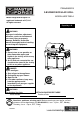
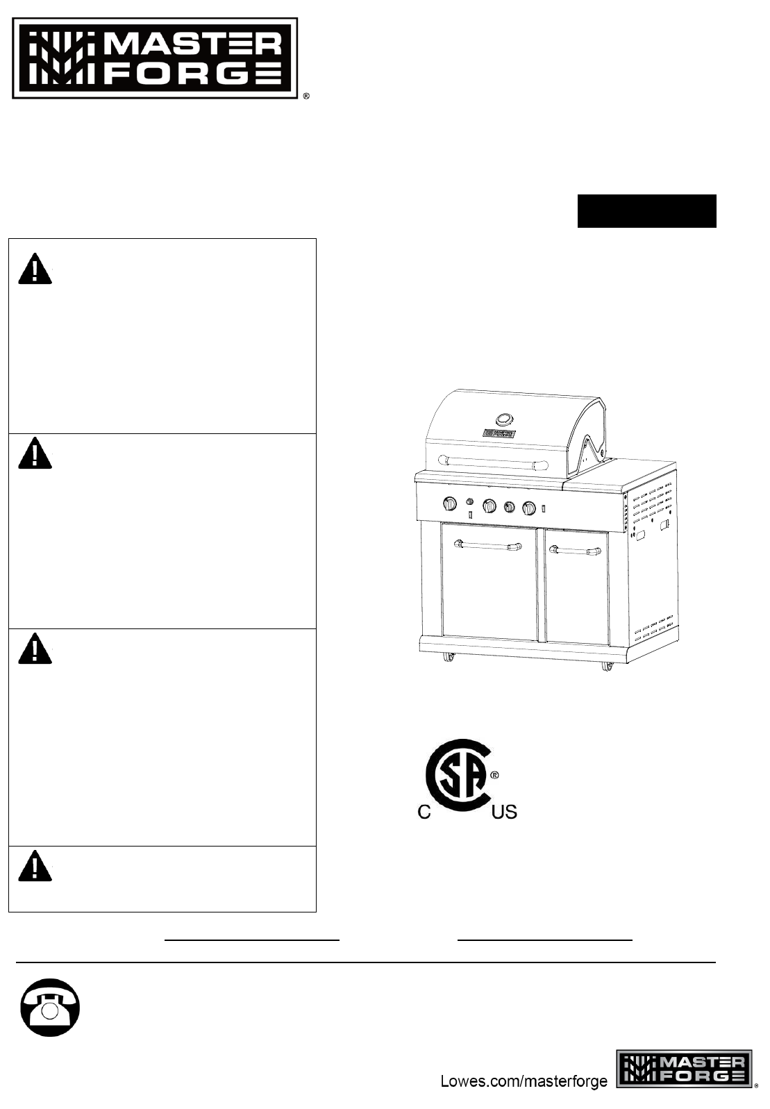
ITEM #0503225 3-BURNER MODULAR GRILL MODEL #BG1793B-A Master Forge & M Design® is a registered trademark of LF, LLC. All rights reserved. Español p. 40 WARNING Improper installation, adjustment, alteration, service or maintenance can cause injury or property damage. Read this instruction manual thoroughly before installing or servicing this equipment. WARNING 1. Do not store or use gasoline or other flammable vapors and liquids in the vicinity of this or any other appliance. 2.
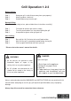
Grill Operation 1-2-3 Before Grilling: Step 1 Step 2 Step 3 Keep your grill a safe distance away from your property.* Always perform a leak test.* Keep children away from the grill. During Grilling: (To avoid tripping safety valves, please follow these instructions carefully!) Step 1 Step 2 Step 3 First open lid and turn gas tank on slowly. Turn only one knob on at a time when lighting the grill. Use protective gloves when grill gets hot.
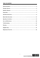
TABLE OF CONTENTS Safety Information…………………………………….………...….………….………….…. ………4 Package Contents…..………………..…..….……...…...................………………………………..6 Hardware Contents……………………………………………………………….……………………7 Preparation…..………………..…………………..….……………………………………………..….7 Assembly Instructions……………………..……………….………………………………………...8 Natural Gas Conversion…………………………………………….............................................12 Operating Instructions…………………………….……...…………………………....................19 Care and Maintenance……………………………….
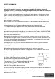
SAFETY INFORMATION Please read and understand this entire manual before attempting to assemble, operate or install the product. If you have any questions regarding the product, please call customer service at 1-800-963-0211 Monday through Thursday from 8:00 a.m. to 6:00 p.m. EST, Friday from 8:00 a.m. to 5:00 p.m. EST. 1. The installation of this appliance must conform with local codes or, in the absence of local codes, with either the National Fuel Gas Code, ANSI Z223.
SAFETY INFORMATION 16. The cylinder used must include a collar to protect the cylinder valve. 17. Do not store a spare LP-gas cylinder under or near this appliance. 18. Never fill the cylinder beyond 80 percent full. 19. If the information in “17” and “18” is not followed exactly, a fire causing death or serious injury may occur. 20.
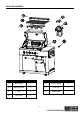
PACKAGE CONTENTS G PART DESCRIPTION QUANTITY PART DESCRIPTION QUANTITY A Main Body 1 E Flame Tamer 3 B Warming Rack 1 F Trash Bin 1 C Grid 3 G Small Knob 1 D Drip Tray 1 6
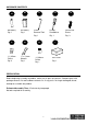
HARDWARE CONTENTS AA BB CC DD AA Battery Qty. 1 9V Battery Qty. 1 Orifice Removal Tool Qty. 1 FF GG HH Φ1.45mm Orifice Qty. 3 17 x 19 mm Wrench Qty. 1 Phillips Screwdriver Qty. 1 EE Conversion Screw Qty. 3 II Φ1.30mm Orifice Qty. 1 Grill Cover Qty. 1 PREPARATION Before beginning assembly of product, make sure all parts are present. Compare parts with package contents list and hardware contents list. If any part is missing or damaged, do not attempt to assemble the product.
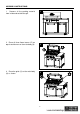
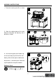
ASSEMBLY INSTRUCTIONS 1. Remove all the packing material from inside and outside the grill. 1 2. Place all three flame tamers (E) on top of each burner on the main body (A). 2 3. Place the grids (C) on the main body (A) as shown.
ASSEMBLY INSTRUCTIONS 4. Place the warming rack (B) as shown. 4 5.Open the cabinet door of the main body (A) and place the drip tray (D) in position as shown. 5 6.Unscrew the igniter push button cap 6 on the main body (A) and feed the “AA” battery (AA) into the igniter module with the positive (+) end facing out. Screw the cap into place on the igniter module.
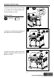
ASSEMBLY INSTRUCTIONS 7. Open the cabinet door of the main body 7 (A) and place the 9V battery (BB) for the control panel light as shown. Hardware Used 9V Battery x1 8 G 8. Screw the small knob (G) into place on the knob bezel on the main body (A). 9. Open the trash bin door of the main body (A) and place the trash bin (F) in position as shown.
ASSEMBLY INSTRUCTIONS 10. Your grill is now assembled.
NATURAL GAS CONVERSION PREPARATION: IMPORTANT: The 10 ft. Natural Gas Hose is NOT INCLUDED. 10 ft. Natural Gas Hose Before beginning conversion, make sure all parts are present. Compare parts with package contents. If any part is missing or damaged, do not attempt to convert. Contact customer service for replacement parts. 1. Turn off gas supply and then remove cap on gas supply side. 2. Recommended: Install a shut-off valve on gas supply side before installing the socket. 3.
NATURAL GAS CONVERSION IMPORTANT: After your grill is converted to natural gas, the working pressure for natural gas is 7 in. water column (WC). Gas pressure is affected by gas line size and the length of gas line run from house. Follow the recommendations in the chart below. From House to Grill Distance Tubing Size Up to 25 ft. 3/8 in. DIA 26 – 50 ft. 1/2 in. DIA 2/3 in. of run 3/4 in. 51 – 100 ft. 1/3 in. of run 1/2 in. More than 101 ft. 3/4 in. DIA WARNING: Place the grill on a flat, level surface.
NATURAL GAS CONVERSION CONVERSION INSTRUCTIONS: Before the conversion, make sure all control knobs are in the OFF position, LP tank valve is closed, and tank is disconnected from regulator and removed from grill. 1. Before the conversion, make sure all control knobs are in the OFF position, LP tank valve is closed, and tank is disconnected from regulator and removed from grill. Next, open lid and remove warming rack, grids and flame tamer. 1 2.
NATURAL GAS CONVERSION 3. Adjust the air shutters of the main burners by loosening the air shutter screws with the Phillips screwdriver (DD). 3 Hardware Used DD Phillips Screwdriver x1 4 4. Remove the LP orifices of all the main burners with the orifice removal tool (CC) and install theΦ1.45mm orifices (FF). CC Hardware Used CC FF Orifice Removal Tool x1 Φ1.45mm Orifice x3 FF 5. Remove the 6 screws at the back of burner box with the Phillips screwdriver (DD).
NATURAL GAS CONVERSION 6. Use the 17 x 19 mm wrench (GG) to remove the hex nut securing the rotisserie burner orifice and hose assembly. Detach the assembly from the bracket. Remove the LP orifice of the rotisserie burner with the orifice removal tool (CC) and install the Φ1.30mm orifice (HH). Reinstall the orifice and hose assembly and the rear panel as stated in Step 5. 6 GG HH Hardware Used GG 17 x 19 mm Wrench CC Orifice Removal Tool HH Φ1.30mm Orifice x1 x1 x1 7. Re-install the burners.
NATURAL GAS CONVERSION 9. Pull off the control knob of the 3 main burners. Use the Phillips screwdriver (DD) to attach the conversion screw (EE) to the back of the knobs. Re-install all the knobs. 9 EE The conversion screw must be attached properly. Failure to tighten the screw will result in improper operation. Hardware Used DD Phillips Screwdriver x1 EE Conversion Screw x3 10. Use the 17 x 19 mm wrench (GG) to remove the LP hose and regulator from the manifold.
NATURAL GAS CONVERSION 11. When converting to natural gas, please be aware that the low heat setting of the main burners is “NG LOW” as shown on the control panel. “LP LOW” setting is not applied when converting to natural gas. 11 LP LOW NG LOW WARNING: Please remember this is an outdoor gas grill. Many areas of the grill generate extreme heat. We have taken every precaution to protect you from the contact areas. However, it is impossible to isolate all high-temperature areas.
OPERATING INSTRUCTIONS Never attach an unregulated gas line to the appliance. Connection to an unregulated gas line can cause excessive heat or fire. Verify the type of gas supply to be used, either Natural Gas (N.G.) or Liquid Propane (L.P.), and make sure the serial plate agrees with that of the supply. Conversion kits are available separately for an additional cost which will enable you to convert your grill from L.P. to N.G. or to convert your grill from N.G. to L.P.
OPERATING INSTRUCTIONS L.P. GAS INSTALLATION Gas grills that are set to operate with L.P. gas come with a high capacity hose and regulator assembly. (Note: Only use the pressure regulator and hose assembly supplied with the grill or a replacement pressure regulator and hose assembly specified by the manufacturer). This assembly is designed to connect directly to a standard 20 lb. L.P. cylinder. L.P. cylinders are not included with the grill. L.P.
OPERATING INSTRUCTIONS 6. Connect the hose and regulator assembly to the tank valve (See Fig. 5). Hand tighten the quick coupling nut clockwise to a full stop. DO NOT use a wrench to tighten because it could damage the quick coupling nut and result in a hazardous condition. Fig. 5 7. Open the tank valve fully counterclockwise. Use a soapy water solution to check all connections for leaks before attempting to light your grill. See “Pre-operation Leak Testing" on page 23.
OPERATING INSTRUCTIONS Disconnecting A Liquid Propane Gas (LP Gas) Tank From Your Grill: 1. Turn the burner knobs and LP gas tank valve to the full OFF position. (Turn clockwise to close.) Fig. 8 2. Detach the hose and regulator assembly from the LP gas tank valve by turning the quick coupling nut counterclockwise. See Fig. 8. CAUTION: When the appliance is not in use, the gas must be turned off at the supply tank. L.P. TANK INFORMATION Never use a dented or rusted L.P.
OPERATING INSTRUCTIONS • The regulator and hose assembly must be inspected before each use of the grill. If there is excessive abrasion or wear or if the hose is cut, it must be replaced prior to the grill being used again. • Cylinders must be stored outdoors out of the reach of children and must not be stored in a building, garage or any other enclosed area. • Only a qualified gas supplier should refill the L.P. tank. • Place dust cap on cylinder valve outlet whenever the cylinder is not in use.
OPERATING INSTRUCTIONS WARNING When leak testing this appliance, make sure to test and tighten all loose connections. A slight leak in the system can result in a low flame or hazardous condition. Most L.P. gas tanks now come equipped with a leak detector mechanism internal to the tank. When gas is allowed to escape rapidly, it shuts off the gas supply. A leak may significantly reduce the gas flow, making the grill difficult to light or causing low flames.
OPERATING INSTRUCTIONS BEFORE AND AFTER LIGHTING 1. Ensure your grill is located on a level surface. 2. Keep the gas grill area clean and free from combustible materials, gasoline, and other flammable vapors and liquids. 3. Ensure nothing is obstructing the flow of combustion and ventilation air. 4. Ensure the ventilation of the cylinder enclosure is free and clear of debris. 5. Visually check burner flames. WARNING Check the gas supply line for cuts, wear or abrasion.
OPERATING INSTRUCTIONS GRILL BURNER LIGHTING Warning: Do not lean over grill when lighting. Turn off LP supply at cylinder when appliance is not in use. Main Burner Lighting Illustration: 1. Check that the control knobs are in the OFF position. 2. Open valve at tank fully by turning counterclockwise. 3. Open lid during lighting. 4. Push the Electronic Ignition down 3 to 4 seconds while turning the GRILL control knob to the HIGH position. The burner should ignite.
OPERATING INSTRUCTIONS If ignition does not take place within 5 seconds, immediately turn the control knob to the OFF position. Wait 5 minutes and repeat step 4 above or refer to match lighting instructions in manual. If the igniter does not function, the burner can be lit by holding a lit match to the burner while the control knob is turned counter-clockwise to “HIGH.” NOTE: After the first use, the stainless steel around the burner will darken.
CARE AND MAINTENANCE INFRARED BURNER CLEANING After each use, it is necessary to burn the bottom infrared burner with the hood open for at least five minutes to vaporize any food drippings or particles. Failure to perform this step will damage the burner. It may occasionally be necessary to brush, blow, or vacuum accumulated ash from the burner surface. Do so carefully and only when the burner is cool.
CARE AND MAINTENANCE GRANITE MAINTENANCE Outdoors can be very harsh on the granite of your grill. Dirt, pollen and even UV rays can affect the granite. Please follow these instructions to preserve the granite’s natural beauty: - Granite is a hard, non-porous natural stone and is relatively not affected by harsh chemicals. However, it is recommended to use a neutral cleaner or stone soap (available in hardware stores or from a stone dealer), or a mild dishwashing liquid and warm water.
CARE AND MAINTENANCE STAINLESS STEEL After initial usage, areas of the grill may discolor from the intense heat given off by the burners. This is normal. Purchase a mild stainless steel cleaner and rub in the direction of the grain of the metal. Specks of grease can gather on the surface of the stainless steel and bake on to the surface and give a worn appearance. For removal, use a non-abrasive oven cleaner in conjunction with a stainless cleaner. NOTE: Always scrub in the direction of the grain.
CARE AND MAINTENANCE Definitions: (+) Guard – Guard is a portion of portable luminaries unit that prevents inadvertent contact with the bulb. It may be integrated with the UV filter or lamp containment barrier or as part of an enclosure or shade. (+) Lamp containment barrier – lamp containment barrier is a portion of a portable luminaries unit that encloses the bulb. (+) UV filter – UV filter is a portion of a portable luminaries unit that limits ultraviolet (UV) emissions. Fig. 10 1.
CARE AND MAINTENANCE ! WARNING The light glass cover should not be in contact with water or any other liquid when it’s warm. Sudden change of temperature may cause cracks on glass cover. ! WARNING To ensure continued protection against electric shock: 1. Connect to properly grounded outlets only. 2. Do not expose to rain. 3. Keep extension cord connections dry and off the ground.
TROUBLESHOOTING Many solutions given here can make your grilling experience safer and more enjoyable. You can also call customer service department at 1-800-963-0211, 8 a.m. - 6 p.m., EST, Monday Thursday, 8 a.m. - 5 p.m., EST, Friday. PROBLEM Grill will not light. Burner flame is yellow and gas odor can be smelled. Excessive flare-up. Burner blows out. POSSIBLE CAUSE 1. The ignition wire came off the electrical igniter/valve. 2.
TROUBLESHOOTING PROBLEM POSSIBLE CAUSE CORRECTIVE ACTION Low heat 1. Low heat is found in natural with the knob gas models. in “HIGH” 2. Ports are blocked. position. 3. LP tank has run out. 1. This model is set for 7 in. natural gas usage. Please check your natural gas supply system to have correct gas pressure. Regulator is not needed for NG model. Check the orifice if you installed NG nozzles. Conversion kit provides the following nozzles: Burner Orifice Size Main Burner Φ1.45mm Rotisserie Burner Φ1.
TROUBLESHOOTING PROBLEM LED control panel lights do not light up. Cooking light will not turn on. POSSIBLE CAUSE CORRECTIVE ACTION 1. No power supply. 2. Damaged wiring or loose connection. 3. Wiring not attached to control panel switch. 4. Defective switch. 5. Defective LEDs. 1. Install 9V battery in the LED battery box. 2. Check all wiring connections between the battery box and the LED. Also check the connections between the LEDs on the control panel. 3.
WARRANTY Proof of purchase is required to access this warranty program, which is in effect from the date of purchase. Customers will be subject to parts, shipping, and handling fees if unable to provide proof of the purchase or after the warranty has expired. If you have any questions or problems, you can call our customer service department at 1-800-963-0211, 8:00 a.m. to 6:00 p.m., EST, Monday - Thursday, 8:00 a.m. to 5:00 p.m., EST, Friday.
EXPLODED VIEW For replacement parts, call our customer service department at 1-800-963-0211, 8 a.m. – 6 p.m., EST, Monday - Thursday, 8 a.m. - 5 p.m., EST, Friday.
REPLACEMENT PARTS LIST PART 1 3 5 7 9 11 13 15 DESCRIPTION Hood Assembly Hood Handle Bracket Hood Silica Pad Hood Axis Cooking Grate Rear Cover Hood Left Lighting Assembly Rear Burner Front Cover Panel QUANTITY 1 2 2 2 3 PART 2 4 6 8 10 1 12 1 14 1 16 DESCRIPTION QUANTITY Hood Handle 1 Hood Handle Washer 2 Thermometer 1 Warming Rack 1 Flame Tamer 3 Rear Infrared Burner 1 Assembly Hood Right Lighting 1 Assembly Rear Burner Ignition 1 Pin Firebox Rear 1 Decorating Panel Firebox Left 1 Supporting Pan
REPLACEMENT PARTS LIST PART 52 54 56 58 60 62 64 DESCRIPTION QUANTITY Cylinder Tray 1 Assembly Left Side Cart Panel 1 Assembly Battery Case 1 Assembly Right Side Cart Panel 1 Assembly Base Panel 1 Assembly Unlocked Castor 2 Hardware Pack 1 PART 53 DESCRIPTION Stage Screw Assembly QUANTITY 1 55 Transformer 1 57 Baffle Plate Bracket 1 59 Cart Real Panel 1 61 63 65 Trash Bin Door Support Panel Locked Castor Grill Cover 1 2 1 Master Forge & M Design® is a registered trademark of LF, LLC.