
Specifications


17
6
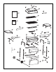
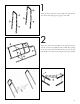
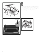
Insert the round opening of the ignitor wire into the pin
located on end of push button ignitor. Remove the nut that
is attached to the igniter. Use this nut to attach the ignitor
(CC) to the control panel (CA), as shown.
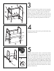
Remove the screws and washers from the valve assembly
(CD) first, and use the same hardware which have been
removed to attach this part(CD) to the control panel (CA).
Position the control knobs (CB) to the valve assembly (CD)
as shown. Assemble the control panel (CA) to the front of
the cart using hardware #3 and #4 (x4). Also simultaneously
assemble the left and right burner box supporting bars (DI
and DJ) to each cart leg using hardware #3 and #4 (x4)
as shown.
CD
C
A
D
J
D
I
Ignitor
Stamped Nut
Back of Cart
CC
CA
CD
DP
D
Q
DR
7
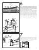
Insert the gas tank retention bracket (DR) into the side sup-
porting bar (DQ) and secure with hardware #16. Assemble
the gas tank heat shield (DP) to the side supporting bar
(DQ) using hardware #1 and #4 (x2)as shown.
Tank
Retainer