TM MC E600 Barbecue With Infrared Side Burner Assembly Manual 85-3102-8 (G45321) Propane 85-3103-6 (G45322) Natural Gas 1 Year limited Warranty Read and save manual for future reference. Assemble your grill immediately. Missing or damaged parts claims must be submitted within 30 days of purchase date. For product inquiries, parts, warranty and troubleshooting support, please call 1-855-453-2150. Manual Revision #: 07312015 AT ANSI Z21.58-2015 / CSA 1.6-2015 ANSI Z21.58-2015 / CSA 1.6-2015 ANSI Z21.
H E A V Y A RTICLE NEEDS 2 TO LIFT THIS MANUAL MUST REMAIN WITH THE PRODUCT AT ALL TIMES To ORDER non-warranty replacement parts or accessories, or to register your warranty, please visit us on the web at www.masterchefbbqs.com CAUTION DANGER Sharp edges. Wear gloves when assembling your grill. Read and follow all safety statements, assembly instructions, use and care directions before attempting to assemble and cook. 1. If you smell Gas: a. Shut off gas to the appliance b. Extinguish any open flame c.
HARDWARE PACK TOOLS NEEDED FOR ASSEMBLY • #2 Phillips screwdriver (long and short) • ¼” Slotted screwdriver (long and short) • Adjustable wrench • Pliers • Rubber Mallot For correct hardware assembly, always position the lock washer between the screw and the flat washer.
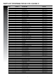
Parts List (propane) for 85-3102-0 (G45321) Key # Quantity Description AA 1 Top lid AB 1 Lid handle AC 1 Thermometer AD 2 Screw for top lid AE 2 Lid bumper, front AF 2 Lid bumper, rear BA 1 Burner box weldment BC 4 Main burner BD 3 Carryover assembly BE 4 Flame tamer BF 2 Stainless steel cooking grate BG 1 Warming rack BH 1 Upper back panel BI 1 Match holder BJ 1 Rotisserie burner BK 1 Wind shield, rotisserie BL 1 Rotisserie burner collector box BM 1 Rotisserie burner, electrode set BN 1 Rotisserie burn
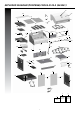
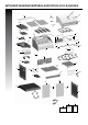
EXPLODED DIAGRAM (PROPANE) FOR 85-3102-0 (G45321) AC BG AA AF BF AB AE DF1 AD BE BC DF2 DG BD BD BD CI BA BJ DD BK BM DE BL DC CA CC DA DB CE1 CE2 CG CB BI BN CD CJ DJ CD BH CF DK DH CK CM EB DI CN CH1 EA CL CH2 EH EG ED EI EI EE EC F4 EF EJ F1 Hardware Pack 3 F2 F3 Assembly Manual SAFETY AND CARE Manual
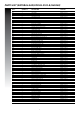
Parts List (natural gas) FOR 85-3103-8 (G45322) Key # Quantity Description Part No.
EXPLODED DIAGRAM (natural gas) FOR 85-3103-8 (G45322) AC BG AA AF BF AB AE DF1 AD BE BC DF2 DG BD BD BM BK BD CI BA BL BJ DD DE DC CD CA CC DA CE1 CD CJ BN CE2 CB DB CG BI DJ BH CF DK DH CK EB CM CN DI CH1 EA CL CH2 EH EG ED EI EI EE EC EF EJ F1 Hardware Pack 5 F2 F3 Assembly Manual SAFETY AND CARE Manual
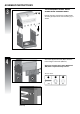
ASSEMBLY INSTRUCTIONS 1 EF Separate the 2 different types of castors: 2 Locking Castors (EE) and 2 Regular Castors (EF). EF EE EE Front ED Attach the Regular Castor (EF) to the front of the Bottom Shelf (ED), and use the Pin Tool (#18) to secure and tighten. Back A Note: Regular Castors (EF) need to be assembled to the front of the Bottom Shelf (ED), and Locking Castors (EE) need to be assembled to the back of the Bottom Shelf (ED), as shown in image A.
ASSEMBLY INSTRUCTIONS 3 THIS STEP REQUIRES 3 PEOPLE. DO NOT ATTEMPT ALONE. EXTREMELY HEAVY! A + B Position the Top Lid Assembly and Burner Box Assembly (A & B) onto the Cart Assembly (C), as shown. C Front View 4 Attach the Upper Back Panel (BH) to both the Left And Right Side Panels (EB & EC). BH Attention: Assembly of the Upper Back Panel (BH) will be completed in Step 8 and 11.
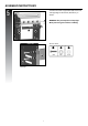
ASSEMBLY INSTRUCTIONS 5 Assemble the Door Support Rail (EA) to the Left and Right Upper Side Panels (EB and EC), as shown. WARNING: This part may have sharp edges. Wear protective gloves when assembling.
ASSEMBLY INSTRUCTIONS 6 Attach the Match Holder (BI) to the left side panel of the Burner Box Assembly. BA You will need: 6 15 79 X1 X1 EA BI EB Front, left side view 7 a. Assemble infrared grease tray rails (DJ) to the infrared support frame (DC) located on the left sear stove side shelf (DA) as shown in figure A. DA You will need: DC 7 X4 A DJ b. Attach the infrared burner lid (DF1) to the left side burner shelf table (DA).
ASSEMBLY INSTRUCTIONS 8 Left side shelf assembly TIP: Do not tighten until all hardware is in place. a. Mount the left side burner side shelf (DA and DB) onto the two support brackets, located on the left, upper side panel of the burner box (BA). DA BA DB b. Assemble the left side burner side shelf (DA and DB) to the upper side panel of the burner box (BA), by positioning hardware through the interior of the burner box (BA), as shown in figure B.
ASSEMBLY INSTRUCTIONS 9 a. Remove the hardware that is pre-assembled to the IR side burner valve (CC), as shown in figure A. Insert the side burner valve stem (CC) through the rear of the left side shelf fascia (DB) and assemble using the hardware removed. DB CC CD A CC B b. Assemble the Side burner control knob (#17) to the Side burner valve (CC).
ASSEMBLY INSTRUCTIONS 10 a. Position the electrode spacer (#19) on the infrared support frame (DC) and then feed the infrared burner electrode (DE) through the opening on the right side of the infrared support frame (DC). Assemble using hardware as shown in figure A. DA DC DE NOTE: the infrared electrode (DE) set can be found attached to the infrared side burner valve (CC). 19 You will need: DB 10 19 X1 X1 A View from above, left side shelf b.
ASSEMBLY INSTRUCTIONS 10 c. Use the side burner Venturi clip (#20) to connect the infrared side burner (DD) to the side burner valve (CC). CC You will need: 20 DD 20 X1 E View from underneath left side shelf d. Position the side burner cooking grate (DG) onto the infrared support frame (DC). DG DC F e. Position the infrared grease tray (DK) onto the infrared grease tray rails (DJ). DJ G DK View from the back, left side f.
ASSEMBLY INSTRUCTIONS 11 Right Side Shelf Assembly TIP: Do not tighten until all hardware is in place. a. Mount the right side shelf (DH and DI) onto the two support brackets, located on the right, upper side panel of the burner box (BA). DH BA b. Assemble the right side shelf (DH and DI) to the upper side panel of the burner box (BA), by positioning hardware through the interior of the burner box, as shown in figure B.
ASSEMBLY INSTRUCTIONS 12 Electronic Ignition Assembly Battery a. Remove the Ignition Battery Cover (CH2) and the plastic nut from the Electronic Ignition Box (CH1). DI + - b. Position the Electronic Igniter Assembly (CH1) through the opening in the Right Side Shelf Fascia (DI) and secure using the plastic nut. CH2 Plastic Nut CH1 A View, under right side shelf c. Insert one “AA” battery into the battery compartment (CH1) with the positive end facing outward, as shown.
ASSEMBLY INSTRUCTIONS 13 a. Remove the hardware that is pre-assembled to the Rotisserie Burner Valve (BN), as shown in figure A. BN Assemble the Rotisserie Burner Valve (BN) to the Right Side Shelf Fascia (DI), using the hardware removed. DI A BN B b. Assemble the Side Burner Control Knob (#17) to the Rotisserie Burner Valve (BN).
ASSEMBLY INSTRUCTIONS 14 Assemble the Heat Shield (CK) to the bottom of the Door Support Rail (EA) and the Upper back panel (BH), as shown in figure A and B.
ASSEMBLY INSTRUCTIONS 15 a. Assemble the Left and Right Tracks (CN and CM) for the Grease Tray (CL), as shown in figure A. EA You will need: 15 CM CN EB EC X2 A Front view CM CN BH B Close up, back view CN CM C Close up, front view b. Insert the Grease Tray (CL) into the opening of the Upper Back Panel (BH).
ASSEMBLY INSTRUCTIONS 16 Assemble the Door Handle (EI) to the Left and Right Door Assembly (EG and EH).
ASSEMBLY INSTRUCTIONS 17 a. Assemble the right door assembly (EH), to the bottom shelf (ED) by inserting the fixed pin (bottom of door) into the hole provided (figure B). EA EH EC ED A EH B ED Close up, bottom of door b. Assemble the top of the door assembly (EH) to the door support rail (EA), by pressing in the door support pin and aligning with the hole located on the top right corner of the door (figure C).
ASSEMBLY INSTRUCTIONS 18 a. Position the Flame Tamers (BE) into the Burner Box (BA).
ASSEMBLY INSTRUCTIONS 19 Place the cooking grates (BF) into the burner box (BA). BF BF 20 Insert the two small positioning rods of the warming rack (BG) into the rear panel of the burner box (BA).
ASSEMBLY INSTRUCTIONS 21 For Propane Model Only For Natural Gas Model, Follow Step 22. a. Attach the Regulator coupling nut (CB) to the LP cylinder valve. CB b. Position the 20 lb propane tank onto the Bottom Shelf (ED), and secure using the bolt (already attached) located on the underside of the Bottom Shelf (ED), as shown in figure C. A ED ATTENTION FOR YOUR SAFETY, DO NOT ATTEMPT TO LIGHT THIS BBQ UNTIL YOU HAVE REVIEWED PAGES 4-8 OF THE MASTER CHEF® SAFETY & CARE MANUAL.
ASSEMBLY INSTRUCTIONS 22 For Natural Gas Model Only Attach the Natural Gas Hose (CB) to the IR Side Burner Valve (CC) as shown. ATTENTION CC In order to complete installation of your Natural Gas BBQ a 1/2” or 3/8” adapter may be required to connect your BBQ’s Natural Gas hose to your home gas supply. Contact your Natural Gas supplier to purchase the necessary part.
Visit www.masterchefbbqs.