
User Manual


10
ASSEMBLY INSTRUCTIONS
8
9
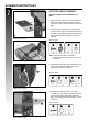
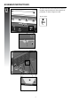
a. Remove the hardware that is pre-assembled
to the Side Burner Valve (DE1), as shown in
gure A
Assemble the Side Burner Valve (DE1) to the
Left Side Shelf Fascia (DB), using the hardware
removed.
b. Assemble the Side Burner Control Knob (#13)
to the Side Burner Valve (DE1).
DE1
DE2
A
DB
YOU WILL NEED:
13
X 1
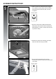
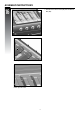
a. Position the Side Burner (DF) through the
opening in the Left Side Burner Drip Pan (DD).
DD
DF
A
B
DE1
DB
13