
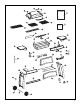
Specifications


19
10
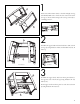
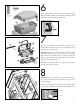
Using Hardware #1 (x2) assemble the valve to the control
panel (CA). Place the control knobs (CB) onto the valves
stems located on the control panel (CA). Assemble the con-
trol panel (CA) to the top of both cart legs (DA & DB) as
shown by using hardware #2 & #3 (x2). Assemble the igniter
(CC) in to the control panel as shown. Connect the elec-
trode wire to the igniter as shown in FIG C.
Very Important: Burner tubes must engage valve openings.
Make sure the valves are aligned with burner tubes.
11
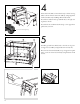
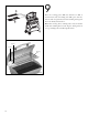
Assemble right and left side shelf (EA & EB) to the cart as
shown by using hardware #1 & #3 (x4) for each side shelf.
Total 8 pcs of hardware #1 & #3 in this step.
EB
EA
C
C
CB
CA
C
D
C
C
CA
C
D