
Service manual


5
Residential Digital Packaged Units GT-PC Series - 60Hz Puron
®
Rev.: 14 June, 2013
Vertical Installation
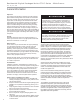
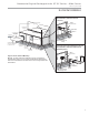
Figure 1: Vertical Unit Mounting Using Ducted Return
Figure 2: Service Access
Air Pad or extruded
polystyrene insulation board
Flexible canvas duct
connector to reduce
noise and vibration
Use turning vanes in
supply transition
Internally insulate supply
duct to reduce noise
Internally insulate return
transition duct to reduce noise
Rounded return
transition
Remove supply duct
flanges from inside blower
compartment and install
on supply air opening of
unit. Do not use a supply
air plenum/duct smaller
than the size of the supply
duct flanges.
Return
Air Inlet
Minumum
Space 10-12”
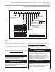
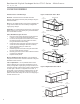
Figure 3: Vertical Sound Attenuation - Free Return
Legend
CAP=Compressor and Control Access Panel
CSP=Optional Compressor Service Panel
BSP=Blower Service Panel
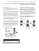
Access Panel
Isometric
View
BSP
CAP
2' (61cm)
Optional
Service
Access
Left Rtn
(right
Opposite)
2' (61cm)
Service
CSP
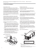
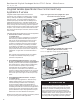
Vertical Unit Location
Packaged units are not designed for outdoor installation.
Locate the unit in an INDOOR area that allows enough space
for service personnel to perform typical maintenance or
repairs without removing the unit from the installed location.
Vertical units are typically installed in a mechanical closet
or basement. Never install units in areas subject to freezing
or where humidity levels could cause cabinet condensation
(such as unconditioned spaces subject to 100% outside air).
Also, provide suffi cient room to make water, electrical, and
duct connection(s).
If the unit is located in a confi ned space, such as a closet,
provisions must be made for return air to freely enter the
space by means of a louvered door or other method. Any
access panel screws that would be diffi cult to remove after
the unit is installed should be removed prior to setting
the unit. Refer to Figures 1 and 2 for typical installation
illustrations. Refer to unit catalog specifi cations for
dimensional data.
1.
Install the unit on a piece of rubber, neoprene or other
mounting pad material for sound isolation. The pad
should be at least 3/8” [10mm] to 1/2” [13mm] in
thickness. Extend the pad beyond all four edges of the
unit.
2. Do not block fi lter access with piping, conduit or
other materials. Refer to unit catalog specifi cations for
dimensional data.
3. Provide access to water valves and fi ttings and
screwdriver access to the unit side panels, discharge
collar and all electrical connections.
Sound Attenuation for Vertical Units
Sound attenuation is achieved by enclosing the unit within a
small mechanical room or a closet. Additional measures for
sound control include the following:
1. Mount the unit so that the return air inlet is 90° to the
return air grille (refer to Figure 3). Install a sound baffl e
as illustrated to reduce line-of sight sound transmitted
through return air grilles.
2.
Mount the unit on a unit isolation pad to minimize
vibration transmission to the building structure. For more
information on unit isolation pads, contact your distributor.