
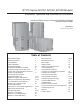
Service manual


3
Residential Digital Packaged Units GT-PC Series - 60Hz Puron
®
Rev.: 14 June, 2013
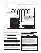
Model Nomenclature: General Overview
WARNING!
WARNING!
CAUTION!
WARNING! To avoid the release of refrigerant into the
atmosphere, the refrigerant circuit of this unit must be
serviced only by technicians who meet local, state, and
federal profi ciency requirements.
CAUTION! To avoid equipment damage, DO NOT use
these units as a source of heating or cooling during the
construction process. The mechanical components and
fi lters will quickly become clogged with construction dirt
and debris, which may cause system damage.
WARNING! All refrigerant discharged from this unit must
be recovered WITHOUT EXCEPTION. Technicians must
follow industry accepted guidelines and all local, state,
and federal statutes for the recovery and disposal of
refrigerants. If a compressor is removed from this unit,
refrigerant circuit oil will remain in the compressor. To
avoid leakage of compressor oil, refrigerant lines of the
compressor must be sealed after it is removed.
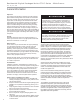
Safety
Warnings, cautions and notices appear throughout this
manual. Read these items carefully before attempting any
installation, service, or troubleshooting of the equipment.
DANGER: Indicates an immediate hazardous situation, which
if not avoided will result in death or serious injury. DANGER
labels on unit access panels must be observed.
WARNING: Indicates a potentially hazardous situation, which
if not avoided could result in death or serious injury.
CAUTION: Indicates a potentially hazardous situation or an
unsafe practice, which if not avoided could result in minor or
moderate injury or product or property damage.
NOTICE: Notifi cation of installation, operation or maintenance
information, which is important, but which is not hazard-
related.
WARNING!
NOTE: Above model nomenclature is a general reference. Consult individual specifi cation sections for detailed information.
D = DXM2
5 = Motorized Valve (Modulating)
Closed Loop Applications, Low System Pressure Drop
6 = Motorized Valve (Modulating)
Open Loop Applications, High System Pressure Drop
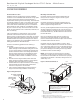
Vertical Downflow YGD
Vertical Upflow YGV
5 0 J0 2 6 CD 3 1 12
4 5 6 7
8
10 11 129
PREFIX
026
UNIT SIZE
038
049
064
AIR FLOW CONFIGURATION
VOLTAGE
CONTROLS
1 = Single Pack, Domestic
PACKAGING
REVISION LEVEL
YGV
1 2 3
YGV = Vertical Upflow Residential
SERIES (Extended Range)
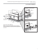
YGH = Horizontal Residential
Horizontal YGH
Option
Return
Discharge
Filter
N
P
W
Y
Right
Right
Left
Left
Left
Back
Right
Back
2”
2”
2”
2”
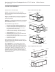
Option
Return
Discharge
Filter
J
K
Left
Right
Top
Top
2”
2”
Motor
ECM
ECM
ECM
ECM
Motor
ECM
ECM
072
1 = Current Revision
WATER CIRCUIT OPTIONS
2 = Internal Flow Controller High Head
13
YGD = Downflow Residential
Option
Return
Discharge
Filter
J
K
Left
Right
Down
Down
2”
2”
Motor
ECM
ECM
3 = 208-230/60/1
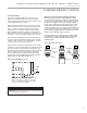
In Position 11 and 12, only the following combinations are available:
Without HWGWith HWG Description
2A2C Internal Flow Controller with Copper Water Coil
5A5C Motorized Modulating Valve with Copper Water Coil
6J6N Motorized Modulating Valve with Cupro-Nickel Water Coil
9 10,
HEAT EXCHANGER OPTIONS
No HWG
HWG W/Pump (Standard)
Copper
Cupro-Nickel
A
C
J
N
WARNING! The Puron
®
Application and Service Manual
should be read and understood before attempting to
service refrigerant circuits with HFC-410A.