
Service manual


15
Residential Digital Packaged Units GT-PC Series - 60Hz Puron
®
Rev.: 14 June, 2013
Multiple Unit Piping and Flushing
Often projects require more than one heat pump. Where
possible, it makes sense for multiple units to share a common
ground loop. Common ground loops for multiple units bring
new challenges including the need to avoid backward fl ow
through inactive units, increased pumping requirements,
and more complex fl ushing needs. Three types of multiple
unit systems are described below along with guidelines for
installation of each type.
Integrated Variable Speed Water Flow Control technology
is a great assist for systems with multiple units. Integrated
Variable Speed Water Flow Control is available in three
different confi gurations:
1. Internal variable-speed pump
2. I
nternal modulating valve for closed loops
3. Internal modulating valve for open loops
The internal modulating valve for open loops version should
never be used on closed loops.
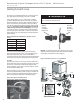
The internal variable speed pump version of Integrated
Variable Speed Water Flow Control includes an internal
Magna variable speed circulator controlled by the DXM2
microprocessor, internal 3-way fl ushing valves, an internal
bladder type expansion tank, and front-mounted pressure
ports that allow access to the pressure drop across the
coaxial heat exchanger only. The Magna pump includes
an internal check valve. The pump curve for the Magna
circulator is shown in Figure 13. The internal expansion tank
will operate as a pressure battery for the geothermal system.
It will absorb fl uid from the loop when loop pressure rises
and inject fl uid into the loop when loop pressure falls. In this
way the expansion tank will help to maintain a more constant
loop pressure and avoid fl at loops due to seasonal pressure
changes in the loop.
When using the internal variable speed pump as the loop
pump in multiple unit installations it is important to ensure
that the variable speed pump can provide adequate fl ow
through the heat pump against the loop head when all units
are operating.
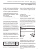
It may be possible to fl ush a multiple unit system through
the unit’s fl ushing valves. Flushing pressure drop of the
valve may be calculated to determine if it is acceptable.
Engineering data for the 3-way fl ushing valves can be found
in Table 2.
For example, if a system includes two 2-ton units and four ¾
loop circuits we can calculate the fl ushing pressure drop as
follows. From Table 1 we know that it will take 4 gpm to fl ush
each ¾” circuit. If there is no provision to isolate the circuits
for fl ushing, we will have to fl ush with a minimum of 4 circuits
x 4 gpm/circuit = 16 gpm total. A check of other piping sizes
used must be done to ensure that 16 gpm total fl ow will fl ush
all piping.
Pressure drop through the fl ushing valve can be calculated
using the following formula.
ΔP = (GPM/Cv)
2
where,
ΔP = pressure drop in psi through the valve while fl ushing
GPM = fl ushing fl ow in gallons per minute
Cv = valve Cv in fl ushing mode
We know from Table 2 that the Cv for the fl ushing valve in a
YG026 is 10.3 in the fl ushing mode (90° fl ow). Therefore,
ΔP = (GPM/Cv)
2
= (16/10.3)
2
= 2.4 psi per valve (there are
two fl ushing valves). So long as the fl ushing pump is able to
provide 16 gpm at the fl ushing pressure drop of the loop plus
the 2.4 x 2 valves = 4.8 psi of the fl ushing valves, the internal
fl ushing valves may be used. If the fl ushing pump is not able
to overcome the pressure drop of the internal fl ushing valves,
then larger external fl ushing valves must be used.
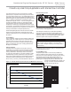
Unit Confi guration
Multiple units with internal variable-speed fl ow controller
and check valve, piped in parallel sharing a common loop
MUST be confi gured for ‘VS PUMP PARALLEL’ in Installer
Settings Menu.
Installer Settings
System Confi g Unit Confi g
Loop Confi g
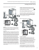
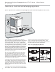
Multiple Units with Internal Flow Controllers
The simplest multiple unit system is one with two (or more)
units utilizing internal Flow Controllers with no external
pumps or fl ushing valves. In this case the units are piped
in parallel and use the internal fl ushing valves to fl ush the
system. The variable speed pump includes an internal check
valve to prevent back (short circuiting) fl ow through the units.
In this case, fl ush the loop through the internal fl ushing
valves in the unit farthest from the loop fi rst. Once the loop is
fl ushed, then change the internal fl ushing valves to fl ush the
heat pump. Next, move the fl ushing cart to the next closest
unit to the loop.
UNIT CONFIGURATION
CURRENT CONFIG YF024
HEAT PUMP FAMILY YF
HEAT PUMP SIZE 024
BLOWER TYPE ECM
LOOP CONFIG VS PUMP
PARALLEL
SELECT OPTION
PREVIOUS SAVE
YG026
026
YG
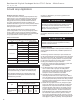
Table 2: Internal 3-Way Flushing Valve Data
Model
Flushing
Connection
Straight
Flow Cv
90°
Flow Cv
TE026 - 038 3/4" FPT 25 10.3
TE049 - 072 1" FPT 58 14.5
YG
YG