
Specifications

Developer’s Serial Bootloader, Rev. 13
FC protocol description
Freescale Semiconductor6
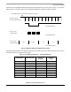
If the MCU transmits to the PC at an unmatched data rate, the PC receives (and accepts) characters that
are different from the 0xFC character. The PC accepts all characters from the mentioned set (0xFF, 0xFE,
0xFC, 0xF8, 0xF0, 0xE0, 0xC0, 0x80, and 0x00). If a character is received, an ACK is immediately sent
back to the MCU. After the MCU recognizes this answer, it enters the next phase, Slave frequency
calibration.
2.2.2 Known MCU communication speed
If the frequency is certain (known at compile time), the MCU will be configured to match exactly the
communication speed of the PC. All characters are received correctly without any distortion.
The MCU sends 0xFC to the PC, which immediately sends an ACK to the MCU. After the ACK is
received, the MCU also (formally) enters the Slave frequency calibration phase.
2.3 Slave frequency calibration
During this phase, the MCU clock is calibrated. Until now, the PC has communicated with the MCU at a
speed that could be from 33% to 300% tolerance. During this phase, the MCU communication speed must
be adjusted to match the PC communication speed.
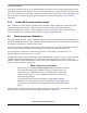
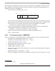
After the PC enters the calibration phase, the no-break timeout starts. If a correct ACK character (0xFC)
is not received within this period, a break character is sent at the communication data rate.
A break character consists of 10 consecutive logical zeros. For example, at a 9600 bd rate, its
high-low-high pulse lasts 10 x 104 s = 1.04 ms.
The MCU then measures the break character length and determines whether its clock is too fast or too slow.
The MCU then makes an adjustment to its system clock (or an adjustment of receive routines if, for
example, software serial communication is used). This can be repeated as many times as required for the
MCU to achieve the proper clock speed.
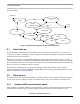
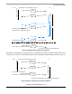
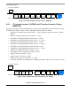
NOTE: Virtual ports workaround
Most of the users are using virtual serial ports and some of these standards
are not able to transfer break calibration character. For this reason, new
feature using zero calibration character was added in place of the break
character pulse (Figure 4). A zero calibration character consists of nine
consecutive logical zeros.
The calibration feature with zero character is implemented in master
application as “short TRIM” (checkbox “short TRIM’, Master applications
user guides). The target must be configured for using short calibration (trim)
pulse.
After the MCU is calibrated to the correct clock (or after the receive routines are calibrated), the ACK
character is sent to the PC to stop sending calibration characters (Figure 4).