
Specifications


MCU slave software
Developer’s Serial Bootloader, Rev. 13
Freescale Semiconductor 45
8.2.1 Software-SCI transmit char routine
A detailed description of the software-SCI transmit and receive subroutines is provided in this section.
They both are based on a 16-bit timer and the output-compare event is polled in the background loop.
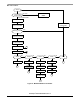
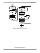
The following figure represents the software-SCI transmit char routine flowchart:
Figure 28. Software-SCI transmit char routine
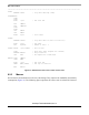
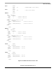
The two routines’ source code is shown in Figure 29. Other than a few counters, a 16-bit ONEBIT variable
is used. It contains the actual length of 1 bit at the current communication speed in 16-bit timer clock
cycles. This variable is initialized during the calibration phase (Slave frequency calibration).
The following figure represents the source code of software-SCI transmit char routine:
ENTER
TEST CARRY
INITIALIZE, FEED AND
RUN 16-BIT TIMER
WAIT FOR
TXD PIN LOW
SET BIT COUNTER
TO 9
TIMER FLAG
SHIFT-OUT TRANSMIT
CHAR INTO CARRY FLAG
TXD PIN LOW
TXD PIN HIGH
CLEAR TIMER FLAG
DECREMENT
BITS AND TEST
TXD PIN HIGH
CLEAR TIMER FLAG
SET
CLEAR
STOP TIMER
EXIT
= 0
TIMER FLAG
RECEIVED?
WAIT FOR
TIMER FLAG
TIMER FLAG
RECEIVED?
NO
YES
NO
YES