
Specifications


Developer’s Serial Bootloader, Rev. 13
MCU slave software
Freescale Semiconductor42
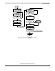
8.1.1 Internal Clock Generator (ICG) — initialization
The ICG is simple to initialize because the ICG is active and the clock monitor is disabled after reset. The
only action required is the modification of ICG multiply register. Then, the ICGS flag (bit 2) of the ICG
control register indicates whether the ICG is stable after the frequency change.
ICGMRINIT EQU $20
MOV #ICGMRINIT,ICGMR ; set 9.8304MHz BUS clock
LOOP: BRCLR 2,ICGCR,LOOP ; wait until ICG stable
8.1.2 Internal Clock Generator — trimming
Even though the trimming routine is in ROM, a small bug renders this code unusable; therefore, the source
code has been taken and inserted in the bootloader code.
Although AN1831/D provides the procedure for calculating the trim factor from the measured CPU speed,
the code itself omits the final doubling of the number of cycles.
* FOLLOWING LOOP IS EXECUTED UNTIL THE END OF THE BREAK SIGNAL. THE BREAK
* SIGNAL LASTS 10 BIT TIMES. IF COMMUNICATING AT f OP /256 BPS, THEN 10 BIT
* TIMES IS 2560 CYCLES. EACH TIME THROUGH THE LOOP IS 10 CYCLES, SO WE
* EXPECT TO EXECUTE THE LOOP 256 TIMES IF THE KX8 IS IN SYNC SERIALLY WITH
* THE HOST. IF WE STAY IN THE LOOP FOR > 256 LOOP CYCLES, THEN THE KX8
* MUST BE RUNNING FASTER THAN EXPECTED, AND NEEDS TO BE SLOWED DOWN. IF WE
* STAY IN THE LOOP FOR < 256 LOOP CYCLES THEN THE KX8 MUST BE RUNNING SLOWER
* THAN EXPECTED AND NEEDS TO BE SPEEDED UP. THE AMOUNT THAT WE CHANGE THE
* CPU SPEED IS EQUAL TO THE NUMBER OF LOOP CYCLES OVER OR UNDER 256. SO IF
* WE GO THROUGH THE LOOP 240 TIMES, THEN WE ARE RUNNING
* (256-240)/256 = 6.25% FAST. EACH INCREMENTAL CHANGE WE MAKE TO THE TRIM REGISTER
* (ICGTR) WILL MAKE A 0.195% CHANGE TO THE INTERNAL CLOCK. THAT IS, INCREMENTING
* THE REGISTER BY ONE OVER THE DEFAULT VALUE OF $80 STORED THERE WILL
* DECREASE THE INTERNAL CLOCK BY 0.195%, AND VICE VERSA.
* NOW EACH EXECUTION OF THE LOOP OVER OR UNDER WHAT IS EXPECTED (256 TIMES)
* REPRESENTS AN ERROR OF 1/256 = .391% ERROR. SO WE'LL NEED TO DOUBLE THE
* NUMBER OF LOOP CYCLES AND USE THIS NUMBER TO CORRECT THE TRIM REGISTER.
* OUR PRECISION FOR TRIMMING IS THEREFORE 0.391%.
The actual code adds an ASLA instruction which doubles the trim factor before the actual write to the ICG
trim register.
ICGTRIM:
CLRX
CLRH
MONPTB4:
BRSET 4,PTB,MONPTB4 ;WAIT FOR BREAK SIGNAL TO START
CHKPTB4:
BRSET 4,PTB,BRKDONE ;(5) GET OUT OF LOOP IF BREAK IS OVER
AIX #1 ;(2) INCREMENT THE COUNTER
BRA CHKPTB4 ;(3) GO BACK AND CHECK SIGNAL AGAIN
BRKDONE:
PSHH
PULA ;PUT HIGH BYTE IN ACC AND WORK WITH A:X
TSTA ;IF MSB OF LOOP CYCLES = 0, THEN BREAK TAKES TOO