
Specifications

Developer’s Serial Bootloader, Rev. 13
FC protocol description
Freescale Semiconductor4
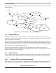
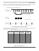
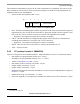
The following is a simplified state diagram that shows separate states of the bootloader, which is described
in this document:
Figure 2. Simplified flow diagram of the bootloader application
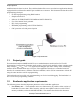
2.1 Initial hook-up
Several methods can be used to enter bootloader mode. Several other solutions use a “certain level on
certain pin” method. For example, if logic 0 appears on an IRQ pin during MCU startup, the bootloader
code starts else the user code starts.
Because the developer’s serial bootloader application must use the lowest number of pins, a “certain
character at a certain time” method is used. This means that the MCU sends out an ACK character through
the serial interface and waits for an answer. If no character is received within the specified time (hook-up
time-out), the process continues with the user code.
If this becomes a limitation for any reason, the user may modify the bootloader code to meet the
application needs (for example, an additional simple IRQ pin test at startup can be implemented). For more
details, see M68HC08 system limitations.
2.2 Clock source
FC protocol allows two scenarios, depending on whether the MCU runs on a known and exact frequency
or uses an RC (resistor, capacitor) clock or an internal clock (or any clock unknown at compile time).
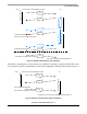
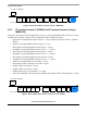
2.2.1 Unknown MCU communication speed
If the frequency is uncertain (unknown at compile time), the MCU will not check whether an incoming
ACK character conforms only to the 0xFC pattern. Because of the MCU clock tolerance, several
RESET
COMMANDS
CALIBRATION
HOOK-UP
COMMUNICATION
READ
WRITE
ERASE
IDENT
QUIT
RESET SOURCE
TEST
CODE
USER
POWER-ON
TIME-OUT