
Specifications

FC protocol, version 5, Kinetis
Developer’s Serial Bootloader, Rev. 13
Freescale Semiconductor 33
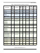
• $r14A -System Device Identification Register (SDID) content ($14A for the K60 Family), r(13-16
bits) is the chip revision number reflecting the current silicon level
• $01 - Number of reprogrammable memory areas
• $0004400 - Start address of the reprogrammable area
• $007FFFF - End address of the reprogrammable area
• $0000000 - Address of the original vector table (1KB)
• $0004000 - Address of the new vector table (1KB)
• $00400 - Length of the MCU erase blocks
• $0080 - Length of the MCU write blocks
7.5 Software reset
If the bootloader must quit and run user code, an MCU reset operation is intentionally executed by using
the system reset sequence bit in register AIRCR (Application Interrupt and Reset Control Register).
During bootloader startup, the System Reset Status (SRS) register is tested. If a power-on-reset is not
detected, the user code starts instead of the bootloader code. This allows a transparent operation of all other
resets with only a short additional delay caused by testing of the SRS register.
7.6 Kinetis system limitations
This section summarizes the limitations that must be considered, when using the bootloader with the user
application.
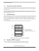
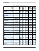
7.6.1 Memory occupied
This version of the bootloader limits the beginning of the flash memory. Due to this, there must be a
modified command linker file (ICF) for the target application and the memory boundary of the user flash
start moved to an address under protected region (for example to address $4400 by K60).
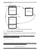
The following figure shows the interrupt vector table relocation for Kinetis K60 MCU: