
Specifications

Developer’s Serial Bootloader, Rev. 13
FC protocol, version 5, Kinetis
Freescale Semiconductor32
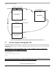
7.2 Interrupt vector table redirection
The FLASH block protection technique also protects the interrupt vector table from being overwritten, so
some method must be used to relocate these vectors to the different locations. To do this, the bootloader
user table is used.
The boundary where the flash memory begins is moved to address of first unprotected region of flash
memory (0x00004000 for Kinetis K60 with 512 KB flash memory) because below this section of memory
the protected bootloader is placed.
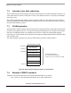
7.3 FLASH protection
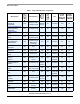
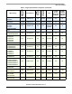
The Kinetis MCU supports flash protection using four 8-bit registers allowing 32 protectable regions. Each
bit in these four registers protects a 1/32 region of the program flash memory. For example, for the Kinetis
K60 with 512 KB flash memory, the smallest protected area is 16 KB. For the bootloader purposes,
protection area of the first flash memory block between addresses $00000000-$00003FFF by Kinetis K60
with 512 KB is used.
The following figure represents the system of flash memory protection in Kinetis MCUs:
Figure 24. System of flash memory protection in Kinetis MCUs
7.4 Example of IDENT command
Example of the memory allocation for the Kinetis K60 bootloader are as follows:
• $C8 - Version 5, read command implemented (bit 8), CRC enabled (bit 7)
Kinetis Flash Memory 512KB
PROTECTABLE AREA 1
PROTECTABLE AREA 2
PROTECTABLE AREA 3
PROTECTABLE AREA 4
PROTECTABLE AREA 31
PROTECTABLE AREA 32
0x00000000
0x007FFFF
...................
32 PROTECTABLE AREAS
IS AVAILABLE IN KINETIS MCUs
(16KB is size of one area on K60 with 512KB)
0x00004000
0x00008000
(BOOTLOADER)