
Specifications


Developer’s Serial Bootloader, Rev. 13
FC protocol, version 5, Kinetis
Freescale Semiconductor30
7 FC protocol, version 5, Kinetis
This section describes features specific to the protocol Version 5 of the bootloader. This was created for a
better compatibility with new Kinetis families of the MCUs. Protocol 4 for the ColdFire MCUs version B
(protected version) is the basis for the Kinetis protocol version 5. The bootloader for the Kinetis MCUs
includes an additional capability for CRC control. The memory allocation is MCU specific, so the meaning
of all variables is explained in the following subsections.
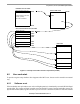
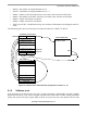
Figure 23 shows the memory allocation typical to the Kinetis K60 devices with the bootloader
preprogrammed. For example, the PK60N512 device memory map includes:
• 495 KB of FLASH memory ($00004000 - $0007FFFF)
• 128 KB of random access memory (RAM) ($001FFE0000-$002001FFFF)
• 16 bytes of nonvolatile registers ($00000400-$0000040F)
• 444 bytes of user-defined vectors ($00000000-$000001B8)
Figure 23. Simplified example of memory allocation in PK60N512
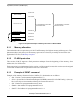
7.1 Memory allocation
The bootloader code occupies the first region of the FLASH memory (the lowest memory address space).
This placement moves at the beginning of the available memory space and it is necessary to shift this
address in the user application linker files (ICF file in IAR and in LCF file in CodeWarrior). The examples
of the ICF and LCF linker files modification are as follows:
USER FLASH (512KB - 16KB)
INTERRUPT VECTOR TABLE
0x00000000
0x0007FFFF
0x00004400
BOOTLOADER
FLASH MEMORY AVAILABLE
FOR USER CODE
FLASH MEMORY AVAILABLE
ON PK60N512
Nonvolatile registers
0x000001C0
0x00000400
Flash memory
INIT_SP
RESET_BL
0x00000410
0x00004000
FLASH PROTECTED
AREA
RELOCATED
INTERRUPT VECTOR TABLE