
Specifications


Developer’s Serial Bootloader, Rev. 13
FC protocol, version 4, ColdFire (V1)
Freescale Semiconductor26
starts instead of the bootloader code. This allows the transparent operation of all other resets with only a
short additional delay caused by testing of the SRS register and executing associated jump instruction.
6.1.5 ColdFire system limitations
This section summarizes the limitations that must be considered when using the bootloader with the user
application.
6.1.5.1 Memory occupied
One major thing is to use the smallest code possible. Typical ColdFire V1 implementations are 1 KB (SCI
version) and 8 KB (USB version for JM version). For the USB version, the biggest part of the source code
is occupied by the USB drivers (5 KB).
The bootloader limits the top of flash memory, and therefore there must be a modified Linker Command
File (LCF) user file. If the LCF file is not set correctly, bootloader will display a warning and the
bootloader will be erased. An example of the modification is shown in the following code block:
# Sample Linker Command File for CodeWarrior for ColdFire MCF51JM128
# Memory ranges
MEMORY {
vectors (RX) : ORIGIN = 0x00000000, LENGTH = 0x00000200
application (RX) : ORIGIN = 0x00000410, LENGTH = 0x0001ABEF //example of memory allocation
buffer (RWX) : ORIGIN = 0x00800000, LENGTH = 0x00000100
userram (RWX) : ORIGIN = 0x00800100, LENGTH = 0x00003F00
}
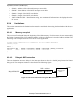
6.1.5.2 Description of the reset transfer
The original vector 1(INIT SP) and vector 2(RESET) are rewritten to the bootloader’s reset and stack
pointer initialization values. The value of the beginning of the user application is programmed into address
0x1C0, and the initialization value of the stack pointer into address 0x1C4. These two values are
reprogrammed every bootloading cycle to the current application values.
6.2 Version B (protected version)
This section describes features that are specific to the Cold Fire V1 implementation version B. The
memory allocation is MCU specific, so the meaning of all variables is explained in this section in detail.
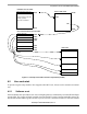
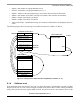
Figure 20 shows the memory allocation typical to the ColdFire V1 devices with the bootloader
pre-programmed. For example, the MCF51JM128 device memory map includes:
• 128 KBof FLASH memory ($00000000-$0001FFFF)
• 16 KB of random access memory (RAM) ($00800000-$00803FFF)
• 16 bytes of nonvolatile registers ($00000400-$0000040F)