
Specifications


Developer’s Serial Bootloader, Rev. 13
FC protocol, version 4, ColdFire (V1)
Freescale Semiconductor24
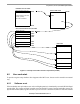
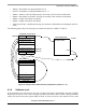
Figure 18. Simplified Example of Memory Allocation in MCF51JM128
6.1.1 Memory allocation
The bootloader code occupies the top of the FLASH memory (the highest memory address space). This
placement reduces only the top of the memory space and it is necessary to modify the end of the user
application LCF file; see Memory occupied.
6.1.2 FLASH protection
This version of MCU supports a flash protection technique from the beginning of the memory, from
address 0x0, for 2 KB sectors.
Flash protection is not implemented in the version A of the protocol, because this version uses the original
vector table at address 0x0 for placement of the user vector table.
6.1.3 Example of IDENT command
Example of the memory allocation for the ColdFire (V1) bootloaders are as follows:
• $84 - Version 4, read command implemented (bit 7)
• $rC16 - System Device Identification Register (SDIDR) content ($C16 for JM Family), r (four top
bits) is the chip revision number reflecting the current silicon level
• $02 - Number of reprogrammable memory areas
• $00000 - Start address of reprogrammable area #1
• $003FF - End address of reprogrammable area #1 + 1
USER FLASH 120 KB
INTERRUPT VECTOR TABLE
0x00000000
0x0001FFFF
0x001FB000
BOOTLOADER
FLASH MEMORY AVAILABLE
FOR USER CODE
FLASH MEMORY AVAILABLE
ON MCF51JM128
Nonvolatile registers
0x000001C0
0x00000400
Flash memory
INIT_SP
RESET_BL
RESET_APP
INIT_SP
0x00000410