
Specifications


Developer’s Serial Bootloader, Rev. 13
FC protocol, version 2, HC9S08 implementation
Freescale Semiconductor20
• $1080 - Start address of reprogrammable memory area #1
• $1800 - End address of reprogrammable memory area #1 + 1
• $182C - Start address of reprogrammable memory area #2
• $FDC0 - End address of reprogrammable memory area #2 + 1
• $FDC0 - Address of relocated interrupt vector table
• $FFC0 - Start address of MCU interrupt vector table
• $0200 - Length of MCU erase block
• $0040 - Length of MCU write block
• ‘GB/GT60’,0 - Identification string, zero terminated. Information to be displayed on PC screen
4.4 Interrupt vector table relocation
The reset and interrupt vectors would be protected if the flash protection is enabled. Vector redirection
(HCS08 hardware feature) allows the user to modify memory allocation of interrupt vector information.
Vector redirection is enabled by programming the NVOPT (nonvolatile option) register. For redirection to
occur, at least some portion but not all of the FLASH memory must be block-protected by programming
the NVPROT (nonvolatile protection) register. All the interrupt vectors (memory locations
$FFC0–$FFFD) are redirected except the reset vector ($FFFE:FFFF).
For example, if 512 bytes of FLASH are protected, the protected address region is from $FE00 through
$FFFF. The interrupt vectors ($FFC0–$FFFD) are redirected to the locations $FDC0–$FDFD.
For example, if an SPI interrupt is taken, the values in the locations $FDE0:FDE1 are used for the vector
instead of the values in the locations $FFE0:FFE1. This allows the user to reprogram the unprotected
portion of the FLASH with new program code, including new interrupt vector values while leaving the
protected area, which includes unchanged default vector locations.
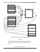
4.4.1 S19 file
Because bootloader operation must be transparent to the user S19 file, another piece of intelligence is built
into the PC master code (instead of the MCU slave). If the record in the interrupt vector table is detected
in the user S19 file, the vector is relocated into the corresponding area in the relocated interrupt vector
table. For example, if the user S19 file contains #2 interrupt vector at address $FFEA, such a vector is
relocated to the $FDEA address in the relocated interrupt vector table.
Using this method, the user S19 file does not need to be modified, but the lower address of the end of
FLASH memory must be considered.
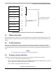
The following figure illustrates HC9S08 interrupt vector table relocation: