
Specifications


Developer’s Serial Bootloader, Rev. 13
FC protocol, version 1, M68HC908 implementation
Freescale Semiconductor14
• $FC80 - Address of Bootloader user table.
• $FFDC - Start address of MCU interrupt vector table.
• $0040 - Length of MCU erase block.
• $0020 - Length of MCU write block.
• 0,0,0,0,0,0,0,0 - Bootloader data. No strictly defined syntax; different M68HC08 implementations
provide different values (for example, the sixth value in the MC68HC908KX8 implementation is
the value of the internal clock generator [ICG] trim register after calibration). All these bootloader
data are then programmed back into the bootloader user table and can be retrieved during all
subsequent starts (for example, to trim the MCU’s ICG to the best-known value before user code
start).
• ‘KX8-IR’,0 - Identification string, zero terminated. Information to be displayed on PC screen.
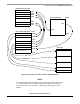
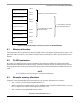
3.3 Interrupt vector table relocation
Because the FLASH block protection technique also protects the interrupt vector table from being
overwritten, some method must be used to relocate these vectors to the different locations. To do this, the
bootloader user table is used. It is a part of memory not protected by the FLBPR, but it is unavailable to
the user program. All standard interrupt vectors are pointing to this table where JMP instructions are
expected to be stored for each interrupt. The only exception is the reset vector that points to the bootloader
code start. When an interrupt occurs, the vector is fetched from protected memory and directs execution
to continue at the corresponding JMP instruction in the bootloader user table.
The following figure shows interrupt vector table relocation for M68HC08 MCUs.