
Specifications

Developer’s Serial Bootloader, Rev. 13
FC protocol description
Freescale Semiconductor10
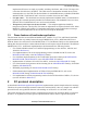
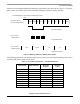
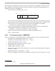
Figure 8. Ident command (FC protocol version 1, M68HC08)
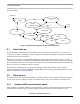
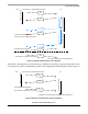
2.4.3 FC protocol version 2 (HCS08) and FC protocol version 3 (large
M68HC08)
Version 2 of the protocol is for HCS08 MCUs; version 3 is for large M68HC08 (HC08 with two or more
FLASH memory banks). In both versions, additional fields are defined as follows:
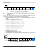
• System device Identification register content — 2 bytes (unused in protocol version 3, coded as
$FFFF)
• Number of reprogrammable memory areas (N) - 1 byte
• Start address of reprogrammable memory area #1 - 2 bytes
• End address of reprogrammable memory area #1 + 1 - 2 bytes
• Start address of reprogrammable memory area #2 - 2 bytes
• End address of reprogrammable memory area #2 + 1 - 2 bytes
• Start address of reprogrammable memory area #N - 2 bytes
• End address of reprogrammable memory area #N + 1 - 2 bytes
• Address of relocated interrupt vector table - 2 bytes
• Start address of MCU interrupt vector table - 2 bytes
• Length of MCU erase block - 2 bytes
• Length of MCU write block - 2 bytes
• Identification string, zero terminated - <n> bytes
• If the CRC capability of serial protocol is enabled, then follows CRC-CCITT checksum - 2 bytes
Figure 9. Ident command (FC protocol versions 2 and 3, HCS08)
I ($49)
VERSION
PC TO MCU COMMAND
MCU TO PC RESPONSE
START
MEM
END
MEM
BOOTLOADER
USER TABLE
INTERRUPT
VECTOR TABLE
ERASE
BLOCK SIZE
WRITE
BLOCK SIZE
ID STRING
0
CAPS.
BOOTLOADER
DATA
AND
CRC
I ($49)
VERSION
PC TO MCU COMMAND
MCU TO PC RESPONSE
START
MEM #1
END
MEM #1
RELOCATED
VECTOR TABLE
INTERRUPT
VECTOR TABLE
ERASE
BLOCK SIZE
WRITE
BLOCK SIZE
ID
0
CAPS.
STRING
#
OF MEM
...
SDID
AND
CRC