
Replacement Part List


“D SERIES” HG
Master Appliance Corp.
2420 18
th
St.
Racine, WI 53403-2381 USA
Tel: 262-633-7791
Email: sales@masterappliance.com
www.masterappliance.com
58278E REV A
pg. 4 of 6
INSTALLATION INSTRUCTIONS
To install the MOTOR:
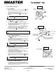
1. Connect the black wire from the motor to the switch Ⓢ (Figure
8).
2. Connect the white motor wire to the piggyback terminal of the
white element connector wire (Figure 8).
3. Slide shrink up over both white wires and connect white wire
from cordset. Position shrink tube Ⓣ over all 3 terminals
(Figure 8).
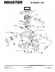
4. Assemble motor into housing and with (2) #6-32 x .50 long
screws Ⓛ (Figure 1). Torque to 16 – 20 in-lbs.
5. Assemble (1) M3 x 0.5 Ⓚ (Figure 1) through back side of
housing and into motor frame at a torque of 2-5 in-lbs.
Excessive torque will warp the motor frame, resulting in reduced
air flow and damage to the motor.
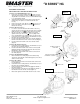
6. Assemble blower wheel onto shaft of motor and tighten set
screw with 1/8 inch hex key. Top of blower wheel hub must be
flush with top of motor shaft. Must not rub against frame of
motor and must not rub against wiring (Figure 9).
7. Ensure electrical barrier Ⓥ is between wiring terminals and
metal enclosure (Figure 8).
To install the ELEMENT CONNECTOR:
1. Connect the black wire from the new element connector to the
switch Ⓝ (Figure 7 & 8).
2. Connect the white motor wire to the piggyback terminal of the
white element connector wire (Figure 8).
3. Slide shrink tube up over both white wires and connect white
wire from cordset (Figure 8). Position shrink tube Ⓣ over all 3
terminals.
To install the CORDSET:
1. Install new cable ties in metal housing (figure 1).
2. Connect the green cordset wire to the enclosure’s ground post
using the green screw (Figure 6).
3. Connect the black cordset wire to the jumper’s piggyback
terminal attached to the switch (Figure 8).
4. Connect the white motor wire to the piggyback terminal of the
white element connector wire (Figure 8).
5. Slide shrink tube up over both white wires and connect white
wire from cordset (Figure 8). Position shrink tube Ⓣ over all 3
terminals.
6. On 220-240V cordsets use supplied cord clamp (figure 10).
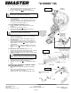
To install the SWITCH / BEZEL ASSEMBLY:
1. Connect the wires to the appropriate switch terminals per
instructions above (Figure 8). The black jumper wire is to wrap
around the white wires from the motor and element connector,
and the green wire from the cordset.
SWITCH
TERMINALS
ELEMENT
CONNECTOR
MOTOR
BLACK WIRE
Ⓢ
JUMPER
BLACK WIRE
BLACK
JUMPER
WIRE
Figure 7
Ⓝ
Figure 9
SHAFT FLUSH WITH
TOP OF FAN HUB
WARNING: Failure to cover the terminals with
shrink tubing
Ⓣ
could result in electrical short
WARNING: Failure to insulate switch & wire terminals
from metal enclosure could result in electrical short
JUMPER, (BLACK WIRE)
WHITE WIRES FROM ELEMENT
CONNECTOR (PIGGYBACK TERMINAL)
MOTOR & CORDSET
SHRINK TUBE
CORDSET BLACK WIRE
ON PIGGYBACK
TERMINAL OF JUMPER
Ⓝ
ELEMENT
CONNECTOR
MOTOR BLACK WIRE
Figure 8
Ⓢ
ELECTRICAL BARRIER
Ⓥ
Ⓣ
WARNING: Failure to cover the terminals with
shrink tubing
Ⓣ
could result in electrical short
WARNING: Failure to cover the terminals with
shrink tubing
Ⓣ
could result in electrical short